You are using an out of date browser. It may not display this or other websites correctly.
You should upgrade or use an alternative browser.
You should upgrade or use an alternative browser.
Taig CNC Mill & Dayjob shop show and tell
- Thread starter iusedtoberich
- Start date
I'm at the family house in Philly for Xmas, where my original shop still lives. The bearings on my tablesaw went out, and I replaced them today. It was not easy! Now, it runs smoothly again.
I had a hammer and saw in my hand from the time I was about 3 years old. My parents got me this tablesaw when I was about 13 or 14 years old, somewhere around 1994.
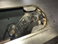
Pulled this sub-assy out of the saw.
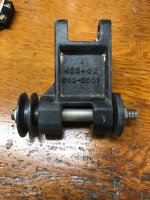
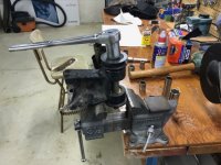

Put in the oven to expand all the metal to help pull the bearing.
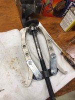
The gear puller couldn't get behind the bearing. I used two screwdrivers to pry it slightly until the gear puller could fit.
I had a hammer and saw in my hand from the time I was about 3 years old. My parents got me this tablesaw when I was about 13 or 14 years old, somewhere around 1994.

Pulled this sub-assy out of the saw.


Put in the oven to expand all the metal to help pull the bearing.

The gear puller couldn't get behind the bearing. I used two screwdrivers to pry it slightly until the gear puller could fit.
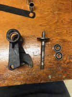
Everything apart. This was not easy!

Spindle in the freezer to shrink it for reassembly with the new bearings.
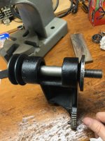
Reassembled. I put some marks on the flange with the vise that I cleaned up as best I could with an oilstone. I didn't have any other way to hold it.
https://youtu.be/k6KYvbPqzB0
7 sec video of what it sounds like now. Just like when it was new
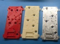
Made this part on the Taig last week. I was shocked how good the tolerances are. Everything is within about .001" to .002".
I first made it on a 3D printer I just got myself for xmas to make sure the design was good (and there were a few changes). Will show more of the 3D printer later. Then I machined it out of ABS to make sure the program was good. Then I made two of them in aluminum, the final material. A PCB gets mounted to it. All the islands sticking up touch hot spots on the PCB, and act as a heatsink.
Time Lapse video of the machining:
https://www.youtube.com/watch?v=4lHGeiHSb10&feature=youtu.be
Video sped super fast, from 2.5 hrs to 5 mins.
I bought this air compressor after reading some of the reviews. It is the quietest air compressor I've ever heard in my life. I'm super amazed at it!
10 sec video of its noise:
https://youtu.be/fKn80WA1Fc0
Model number info:
California Air Tools 8010
Amazon has it for 170 with free shipping.
*I have no affiliation with the company.
Wow, that is quiet
When you control the axis for the final passes, so write a finish path in such a way that the axis is always going the same way to make the axis position for the last cut, and make the last cut fine, so less than 3 thou of wall or 3 thou in depth, you will get a very remarkable repeatable product. Some cam systems don't allow for such things, and I found that writing the finish path in gcode will get you to be very repeatable on a machine that otherwise is not. Basically take the assumption that you have 1/4 turn of backlash and need to wind in the smae direction so that it is not a factor in the axis position. Not easily possible with inclined geometries etc, but you get the idea.
Hi all, I have been working on the cnc a lot the past few weeks. I joined a Facebook group specifically for the Taig mill. In that group, I saw some people were upgrading the spindle motor with a "knockoff" industrial sewing machine servo motor. I'm almost done installing it on my machine. Here are a few pictures:
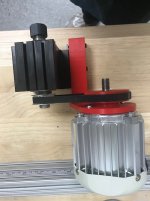
Someone in the FB group already had a design worked out to mount the motor, and provided the files. I printed them on my new 3D printer I got from Amazon in December, to see how they fit. I changed the design slightly, and then went about making them in aluminum.
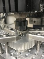
The pulley needs to have its bore opened up.
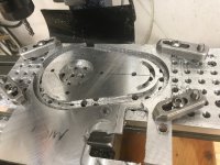
Here I'm machining the motor plate.
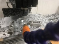
Here I'm machining a spacer that goes under the pulley.
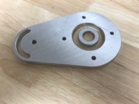
Here is the motor plate and spacer finished.

Someone in the FB group already had a design worked out to mount the motor, and provided the files. I printed them on my new 3D printer I got from Amazon in December, to see how they fit. I changed the design slightly, and then went about making them in aluminum.

The pulley needs to have its bore opened up.

Here I'm machining the motor plate.

Here I'm machining a spacer that goes under the pulley.

Here is the motor plate and spacer finished.
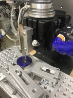
I came up with this broaching tooling using a lathe parting tool from my cue lathe
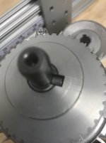
The fit was great. This wasn't really necessary. Everyone else in the group used a setscrew. I just wanted to do it for the fun and challange.
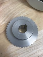
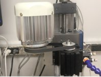
Here is what it looks like now. I haven't machined with it yet, as I'm still working on the control box. It will have variable speed. This motor is way smaller than the original one, and is more powerful.
Here is the control box. The sewing machine motor has a foot control. That is replaced with a knob for the variable speed. In the top window, will go the LCD from the sewing machine drive box. That will display the RPM of the motor.
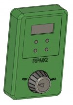
Here is the control box I designed. Its my first design in Fusion 360. I've been using Fusion for a few months for CAM, but never for CAD. (In my day job I use another CAD software for 20 years...). I'm getting the hang of it.
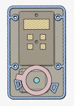
Section showing the hard stops for the knob rotation.
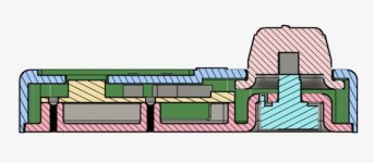
Section through the centerline.
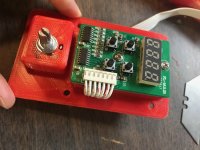
Inside.
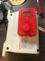
First printout. Needs some adjustments. It will be attached to the sewing machine motor drive box shown here with screws.

Here is the control box I designed. Its my first design in Fusion 360. I've been using Fusion for a few months for CAM, but never for CAD. (In my day job I use another CAD software for 20 years...). I'm getting the hang of it.

Section showing the hard stops for the knob rotation.

Section through the centerline.

Inside.

First printout. Needs some adjustments. It will be attached to the sewing machine motor drive box shown here with screws.
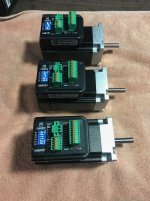
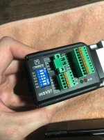
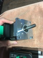
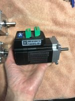
I'm also going to upgrade my Xylotex drive and open loop stepper motors. I was going to go with closed loop stepper motors, but then came across real servo motors for less money. I paid $255 shipped from Alibaba for qty 3 servo motors. I don't know how to set them up yet, and won't have time to get to them for a bit. But take a look at the pictures. Type in "ihsv57" or "JMC servo" on YouTube, and you will come across a few videos showing them off. I think they will end up being the new standard of DIY CNC machines. Cheaper, and better. It will just take some time for the DIY'rs to figure out the tuning of them. Oh, they also come with the drive. That's the bump sticking out the side. So you would just need a power supply and the motion control board in the cnc electronics box. This would be cheaper than a G540 based open loop system (I think...). They come in 4 sizes for the power. I got the smallest one. I can cut reliably now at 30IPM in aluminum, at full flute depth (but shallow width of cut high speed machining). I hope to get up to 60IPM cutting after the servos are in. Oh, and my acceleration is super slow now, that should see a huge jump. These servos coupled with the new spindle which is faster and more powerful, I hope to be able to cut my cycle time 3 or 4 times faster that current.


Very impressive stuff. Nice to see such attention to aesthetics on the control box and the computer models.
Thank you
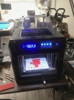
This morning the latest iteration was done. I took some pics to show the printer. The printer is in my house. My company ran out of cash and wouldn't buy one. This was $1200 on amazon, and I'm pretty happy with it. The machines at my prior day job were between 75k and 400k. They print better than this one, for sure, but this one is good enough.
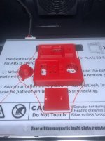
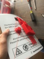
One of the biggest advantages to the printers for companies with big pockets after having parts made from both, imo, is the big boy ones print the support material in a different material. The parts are placed in a bath that dissolves the support material only. It takes a lot of hand work to clean up the parts from this hobby level machine. Scraping, sanding, prying, etc. But, for the price, its great.
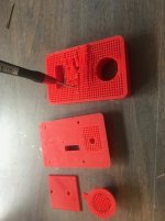
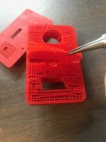
One of the biggest advantages to the printers for companies with big pockets after having parts made from both, imo, is the big boy ones print the support material in a different material. The parts are placed in a bath that dissolves the support material only. It takes a lot of hand work to clean up the parts from this hobby level machine. Scraping, sanding, prying, etc. But, for the price, its great.


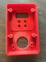
Example of sanding I had to do on the inside to get the printed part to be like the CAD.
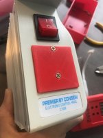
This is where the LCD came from. I made a cover to cover the holes there now. The way I'm going to mount this on my mill, the LCD would have been facing the ground if I left it as-is. And I needed to add a potentiometer anyway, so that is the reason I made a new box that will attach to this box.
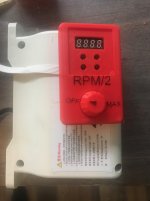
It came out good. I will take it to the office this week where the Taig is, and mount it. I have to adjust the hard stop locations on the knob. This motor and potentiometer combo, the motor start and motor max positions don't correspond with the end limits on the potentiometer. So the hard stops I made will have to be tweaked to provide those limits properly. I can't do that until I'm at the machine with the motor powered up. After that, I will print one last one (hopefully) in white color. By that time, I hope my hand doesn't slip again when blackening the tops of the letters. ha ha.
Wow, you have been busy!
I, too, have been using the Consew motors - I have 1 on my repair lathe and one spare to install on my CNC tapering rig, just waiting for some down time to do that. I also belong to the Taig Mill FB group that you referenced.
On my CNC rig, I started with open-loop steppers, graduated to closed-loop steppers and have an iHSV57 motor to start testing with.
One question if you don't mind:
When you replaced the Hall Effects speed control on the Consew motor with the potentiometer, were you able to get better resolution than 100rpm on the LED readout? I used a 10K variable potentiometer and still get the jumps.
Thanks and keep the build posts coming.
Gary
Wow, you have been busy!
I, too, have been using the Consew motors - I have 1 on my repair lathe and one spare to install on my CNC tapering rig, just waiting for some down time to do that. I also belong to the Taig Mill FB group that you referenced.
On my CNC rig, I started with open-loop steppers, graduated to closed-loop steppers and have an iHSV57 motor to start testing with.
One question if you don't mind:
When you replaced the Hall Effects speed control on the Consew motor with the potentiometer, were you able to get better resolution than 100rpm on the LED readout? I used a 10K variable potentiometer and still get the jumps.
Thanks and keep the build posts coming.
Gary
Great. Would be nice to hear how your iHSV57 servo motors turn out. I bought the 100W version. I think the 180W version is the most popular. I got the less powerful version only because the motor is shorter in length. The price difference was negligible.
Its been a couple of weeks since I had the spindle powered up, but I recall it incremented by 100 RPM. I think it also started at 300 or 400 as well, not zero.
There is one person in the taig FB group just yesterday he made a post on all the steps necessary to put an encoder on the consew motor, and have it controlled by the CNC software. That would probably get RPM reading to the single digits. But for me, at least now, I just wanted a simple knob
I'm also going to upgrade my Xylotex drive and open loop stepper motors. I was going to go with closed loop stepper motors, but then came across real servo motors for less money. I paid $255 shipped from Alibaba for qty 3 servo motors. I don't know how to set them up yet, and won't have time to get to them for a bit. But take a look at the pictures. Type in "ihsv57" or "JMC servo" on YouTube, and you will come across a few videos showing them off. I think they will end up being the new standard of DIY CNC machines. Cheaper, and better. It will just take some time for the DIY'rs to figure out the tuning of them. Oh, they also come with the drive. That's the bump sticking out the side. So you would just need a power supply and the motion control board in the cnc electronics box. This would be cheaper than a G540 based open loop system (I think...). They come in 4 sizes for the power. I got the smallest one. I can cut reliably now at 30IPM in aluminum, at full flute depth (but shallow width of cut high speed machining). I hope to get up to 60IPM cutting after the servos are in. Oh, and my acceleration is super slow now, that should see a huge jump. These servos coupled with the new spindle which is faster and more powerful, I hope to be able to cut my cycle time 3 or 4 times faster that current.
View attachment 543294
View attachment 543295
View attachment 543296
View attachment 543297
That looks seriously good.
Yeah, I'm super excited. Here are two short YouTube videos showing them off and how fast they move.
https://www.youtube.com/watch?v=xyVr35pgx7s
https://www.youtube.com/watch?v=6ukY3XcOa6M
https://www.youtube.com/watch?v=xyVr35pgx7s
https://www.youtube.com/watch?v=6ukY3XcOa6M
I finished the Consew modifications a couple weeks ago. Here is a 30 sec video showing it.
https://www.youtube.com/watch?v=HCMMdCeRB8A&feature=youtu.be
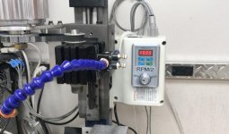
https://www.youtube.com/watch?v=HCMMdCeRB8A&feature=youtu.be

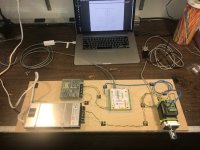
I've been working on this the past few days at home. I have the software working, and the motor spins ok on the bench. I will take it to the office this week and try it on the Taig X axis. If all goes well, I will have to design an enclosure for everything on the board, plus more items I'm sure, and put it all together. That will be sometime later if I'm not busy with other things.
