Quick question, Anyone have a method to quickly center your cnc cutter over the cue. Seems like I generally eyeball it. I cut a piece of wood of fit between the table and the outside of the cnc frame that seems like it puts if back about the same position every time but im still not sure Im dead nuts. Thanks for any advise. Mark
You are using an out of date browser. It may not display this or other websites correctly.
You should upgrade or use an alternative browser.
You should upgrade or use an alternative browser.
cnc Centering
- Thread starter kiinstructor
- Start date
CNC Centering
To find dead center on your CNC machine. Put broken bit leaving only the 1/8 inch solid shank sticking out. Bring that down and touch the outside edge of the cue or better yet the outside edge of a ground dowel pin. Lets say the pin is 1/2 inch and the center is half the diameter. So the center is .250" and the bit is .125" and half of that is .0625. Add .0625 and .250 together for a total of .3125". That is how far you are from dead center. Raise your Z axis and jog over .3125" and zero it on dead center.
To find dead center on your CNC machine. Put broken bit leaving only the 1/8 inch solid shank sticking out. Bring that down and touch the outside edge of the cue or better yet the outside edge of a ground dowel pin. Lets say the pin is 1/2 inch and the center is half the diameter. So the center is .250" and the bit is .125" and half of that is .0625. Add .0625 and .250 together for a total of .3125". That is how far you are from dead center. Raise your Z axis and jog over .3125" and zero it on dead center.
Last edited:
Using an 1/8" or wider bit, mill a small flat on top of a freshly-turned cylinder. Without rotating the indexer any, switch to an engraving bit and scribe a short line that is equidistant from each edge of the flat. When you get your scribe line perfectly centered you will also be perfectly centered on the cylinder.
TW
CNC Centering
To find dead center on your CNC machine. Put broken bit leaving only the 1/8 inch solid shank sticking out. Bring that down and touch the outside edge of the cue or better yet the outside edge of a ground dowel pin. Lets say the pin is 1/2 inch and the center is half the diameter. So the center is .250" and the bit is .125" and half of that is .0625. Add .0625 and .250 together for a total of .3125". That is how far you are from dead center. Raise your Z axis and jog over .3125" and zero it on dead center.
If you're afraid of crashing into the pin, you can use a piece of paper/aluminum foil/shim/whatever as a feeler instead of touching the actual pin.
It's too bad you're not setup to do a touch off. If you can, setting up a touch off would be high on my list of things to do. Then you can automatically zero your tool height, and if you don't trust your home position you can do a touch off and get that every session too and it'll always be perfect. If you do it right, you can even do tool height compensation, i.e. have one tool for hogging out cavities, switch to a smaller tool for details, touch off and finish, and it'll be perfect.
CNC Centering
To find dead center on your CNC machine. Put broken bit leaving only the 1/8 inch solid shank sticking out. Bring that down and touch the outside edge of the cue or better yet the outside edge of a ground dowel pin. Lets say the pin is 1/2 inch and the center is half the diameter. So the center is .250" and the bit is .125" and half of that is .0625. Add .0625 and .250 together for a total of .3125". That is how far you are from dead center. Raise your Z axis and jog over .3125" and zero it on dead center.
just to add to that....... assuming you are using Mach 3... touch one side of the cue and then zero that axis............ touch the other side ...... go the DRO in Mach3 for that axis and type /2..... hit enter and the distance with be divided by 2................. press........."go to zero"................... the machine will go to the center of the cue
Kim.
Can you not use an edge finder and the side of your headstock? Tommy D.
You can certainly use an edge finder if you can slow your spindle way down, but you would never do it off the headstock. It's not nearly accurate enough for that. Even the sides of the chuck wouldn't be accurate.
Building mine to run off a centering camera...displays to either a tablet or the main pc, once you get the offsets calibrated from the camera center to the cutter center it's just inputting the offsets into Mach then it will automatically calibrate zero... just my .02 ")

Can you not use an edge finder and the side of your headstock? Tommy D.
We use an edge finder for our metal milling machine. But I do not have an edge finder that will go into an 1/8" collet for our smaller CNC machine.
Last edited:
Using an 1/8" or wider bit, mill a small flat on top of a freshly-turned cylinder. Without rotating the indexer any, switch to an engraving bit and scribe a short line that is equidistant from each edge of the flat. When you get your scribe line perfectly centered you will also be perfectly centered on the cylinder.
TW
This is basically how I do it on my manual pantomill inlay machine.
You can certainly use an edge finder if you can slow your spindle way down, but you would never do it off the headstock. It's not nearly accurate enough for that. Even the sides of the chuck wouldn't be accurate.
Actually, you can. Pick a vertical sidewall on your headstock (or bolt on a small metal block) and then set your spindle one time to true top-dead-center - using one of the methods explained in previous posts. Move over to a location that allows you to mill a flat vertical surface on your headstock, and note your Y-axis location readout after your final cleanup passes (this assumes "Y" is your side-to-side axis)
Now, using a piece of ground drill rod (or carbide blank, or shank of broken bit, or...) that exactly matches the bit you used to mill your reference surface (above), you can very accurately touch-off your spindle to the sidewall you milled for reference surface, and then use that DRO number to relocate to Top-Dead-Ccenter.
If you are using a stepper motor on your Y-axis, and if that stepper motor has a double-ended shaft, you can permanently mount a reference disk to the outboard shaft, and a reference block immediately adjacent to that disk. Once you have positioned the spindle so it is TDC, power down your machine. Now power it back up. This necessary off-on sequence will force the stepper motor on your Y-axis to seek a full step position that is as close to your desired TDC location as physically possible.
Now you are here: you have your spindle located at Top-Dead-Center and your Y-axis spindle "locked on" at a full-step position. Using a straight edge and a sharp scribe, strike a witness line from the center of your outboard shaft, across your reference disk and reference block. This will give you a mark you can very accurately use to reset TDC whenever you power up you machine. Assuming a Y-axis drive screw of at least 5 rpi resolution (.200"), the next full step on either side of TDC will put your witness mark NOTICEABLY misaligned, making your centering operation extremely easy and repeatable.
I believe Jake (and some others here) got a chance to see this method used on a machine I built for Richard Black several years ago. That worked flawlessly until I later replaced the steppers with servo motors, and he now uses a different method for locating TDC.
TW
Thanks Guys for all your help. Seems like there is a few different ways to determine the center of a work piece. My machine has a fairly long point on the forearm end of the cue. About 1 1/2 inches long x .4 diameter. If Im understanding this right. I can use a 1/8 inch dowel pin in my collet and move to oneside of the point and zero that. Then raise it and move it .625 for 1/2 the pin diameter and .2 for the point diameter and that should be center. I have mastercam version 8. A much older version. Is there some way I can home this position so that I can always come to this position? Thanks again for all your help. Mark
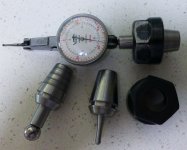
I would set it up so you know where the spindle of the set up is. I like using dial indicators and have an indicator set up in a solid collet with a nut for the ER20 that my router has. You can scan one side , then lift up and scan the other side, 1/2 the difference you will be in the middle. My router does not home Zero all that well, it is inside about 0.1mm or 4 thou in inches mode. In Mach 3 I have made a 4mm ball that sticks out from the spindle 20mm, it is a solid piece with it's dedicated nut as well. There is also a 7/16 ball bearing on a mount as well that sticks out 1 inch from the collet. I can use the touch probe setting and it will touch down onto the circuit board and will be the 1.50 mm thickness of the board away from the part for either height setting or for side positioning in a vice for example.
Once you have the centre of the part or the centre line of the axis of the setup, a pin pointer can be used to get the radial position correct on the part or any of the other mentioned ways of setting up. The cameras work well too if they are correctly set for that machine.
Neil
Once you have the centre of the part or the centre line of the axis of the setup, a pin pointer can be used to get the radial position correct on the part or any of the other mentioned ways of setting up. The cameras work well too if they are correctly set for that machine.
Neil
Attachments
just to add to that....... assuming you are using Mach 3... touch one side of the cue and then zero that axis............ touch the other side ...... go the DRO in Mach3 for that axis and type /2..... hit enter and the distance with be divided by 2................. press........."go to zero"................... the machine will go to the center of the cue
Kim.
nice, simple solution.
Once you find dead center, turn off your machine, and run the Y axis to a hard stop. Fire it back up, and then note the exact measurement to return to TDC. Do it a couple of times, and if it's reliable, you can find TDC really fast by simply going to the hard stop, then jogging over the proper amount.
I have only run commercial cnc equipment so am not familiar with the small gantry type cnc's but am I to assume that these machines rarely have limit switches? In all the cnc's I have run you can store work offsets in your control and the machine will return to those positions when called in your program. So every time tyou shut your machine off you lose your work position? How do you determine machine home position, and is it not repeatable?
I have only run commercial cnc equipment so am not familiar with the small gantry type cnc's but am I to assume that these machines rarely have limit switches? In all the cnc's I have run you can store work offsets in your control and the machine will return to those positions when called in your program. So every time tyou shut your machine off you lose your work position? How do you determine machine home position, and is it not repeatable?
A lot of them either don't have limit switches, have poor limit switches, or have poor homing routines that aren't repeatable. If anyone is interested, I'll put on my automation hat and post what a good, reliable homing routine looks like, and the kind of switches that will make it possible to get .001" or better repeatability.
A lot of them either don't have limit switches, have poor limit switches, or have poor homing routines that aren't repeatable. If anyone is interested, I'll put on my automation hat and post what a good, reliable homing routine looks like, and the kind of switches that will make it possible to get .001" or better repeatability.
This has been discussed in depth but would love to hear your take on it as homing with mach is gangster as hell unless you have a motion controller that will support index output from drive. AZ's resident cnc guru's maintain that opto's "flag switches" are the most accurate and repeatable. I've physically observed these and agree with them however i dont care for all the pull up/down resistors and the gymnastics involved in wiring them. PMDX used to make a simple 3 wire 24v unit that was awesome but discontinued them. I'm currently using one on my rotary and it works flawless. My linear axis have the chinese inductive proxis and are repeatable to within a few tenths at worst. (which is way good for me) I do have servos that i soon intend to retrofit that have home on index output with a motion controller that will interface them.
I think i remember you from the zone where you were working on a Hicon or kflop? If that was you then your knowledge would be met with a warm welcome.
Yes, that was me and it was with kflop. My background actually happens to be with automation and controls. The best way of homing is with some sort of switch (doesn't really matter what kind of switch), and an encoder that has a index pulse. Then you simply run into the home switch, and then back off until you get the index pulse. Of course, you need to be careful that the index pulse isn't "too close" to the home switch. If it is, you need to move the home switch, or better, setup your routine so that if you're within so many counts of the switch when the pulse goes high you use the NEXT index pulse.
But most of us just use open loop steppers. The proximity switches are awesome for this because they're very repeatable AND they have a lot of hysteresis. This allows you to do a homing routine like this:
1) rapidly drive each axis into the limit sensor (rapidly is a relative term here...fast enough it's not painful, but not so fast that it's scary when your controller shuts everything down cold). You can drive all axis at the same time
2) re-enable your axis
3) SLOWLY jog off the axis until the limit switch goes off. Do this one axis at a time. If possible, switch your home logic so that the controller itself actually does the limit switch monitoring/shutdown, and you're just monitoring for the limit condition so you know it's OK to continue. Zero the axis and move on to the next one.
Doing it like this I was able to achieve homing accuracy to well within .001", and it was stable for long periods of time. Every so often you'll want to go and re-calibrate your stations, at least just to be sure.
Not only will this get you a reliable home position, but because of the hysteresis in the sensor you're actually able to use (0,0) because the sensor will NOT trigger at your home position when you approach it from the positive side. So you get to jog to the home position quickly, step off slowly to get a very accurate 0, and that zero is very close to the optimal 0 for the system that gets you the biggest work envelope.
If you're going to use flags, which may not have the hysteresis, then what you want to do to make it painless is:
1) jog quick to the flag
2) step off relatively quickly until the flag goes off, and a little bit past that
3) jog SLOWLY to the flag, preferably with the controller monitoring the flag status and controlling shutdown
4) when you hit the flag, jog off the flag a number of steps and set your home position there
You need to jog off the flag or your (0,0) position will not be usable. There will be ambiguity if (0,0) sets off the flag or not. Best to jog off a tiny bit and reduce your work envelope than to have an unusable coordinate.
What makes homing so painful, often times, is missing the idea that you don't have to home on the initial jog to the flag. Get to your basic home position quickly so it's not so painful, but when you actually grab your zero do it VERY slowly. If you really want to, you can go one step at a time, check the sensor, step, check the sensor. That will alleviate any latency issues, but if you do that when your axis is in some random position, it will take forever. Find the rough flag position first, and then go as slowly as you need to go to get whatever accuracy you need.
Just FYI, though: If I build another CNC machine, it will have encoders on it with an index pulse, even if I end up running it open loop. For a little extra wiring, and a few bucks, it's worth having the encoder just for the index pulse IMHO and then all this nonsense goes away. It's the professional way of doing it, and had I thought about when I originally built it that's what I would have done. I hadn't anticipated how useful an absolute (0,0) would be when I originally built it. I'll also mention that I didn't bother putting any limits on my Z axis at all. I'm not recommending that, but I thought it was completely useless given that I didn't have fancy tooling and I would be doing a touch off no matter what anyhow.
I'll also say that having a touch off routine that allows you to match heights of different tools, using a fixed touch plate, is invaluable. I think Mach3 has some canned routines available to do it. I had to invent some for KFlop but it was worth every minute.
Last edited:
yep, your one of those lucky guys who's background gives you a true understanding of this technical stuff.
I wish i was just ok with the fact that i know how to hook up the switches and make it repeatable beyond my actual needs but i'm not. For some stupid reason i desire to understand why.
So in laymans terms.....Hysterisis in this case makes the switch more potent per se? Effectively allowing it to consistently and more quickly sense the object and also transmit the signal? After all, where mach is concerned its only looking for a signal and latency can be the only variable?
As far as your jogging routine.....i guess i totally agree but man does that sound like a pain in the ass. So to sum it up, your going slow (jogging / slow rapid) into the switch to defeat any high speed deceleration or inertia thats present when switch is triggered? Since the axis can't actually come to a complete stop when signaled? But theoretically if your routine was to home the machine at 100 ipm, and all things mechanical were pretty solid (without slop) then wouldnt it consistently overshoot? I guess the only bad thing that could happen would be to have a stepper miss steps if it were coming to a complete stop similar to hitting a limit switch?