3D Printed Pool Objects

iusedtoberich

AzB Silver Member
Silver Member
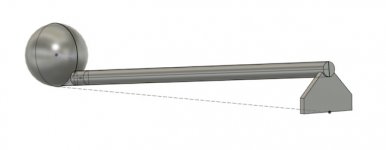
I'm working on a 3D model of at CB with a stick striking it, to print, and play around with. Just thought I'd share the process for a conversation topic. CAD I'm using is called Fusion 360. Its legit free for personal use if anyone wants to fool around with it. And there are tons and tons of YouTube videos on how to use it. I've been using it for a few months, and really like it.
Screen Shot 2020-04-12 at 12.17.40 PM (1).jpeg
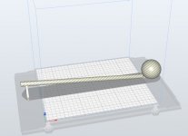
This is what it looks like. It will be able to sit on the table and be in the correct orientation. Purpose is to see how a perfect draw shot looks on camera at different parts of the table and at different camera angles. Where the shaft is cut off is my bridge length.
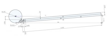
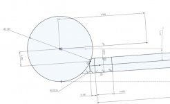
Screen Shot 2020-04-12 at 12.18.12 PM (1).jpeg
These are the dimensions used to make it. The tip contact point is at the miscue limit. The bridge length is 13.5", which is my personal bridge length (I measured it). And the elevation of my bridge for a draw shot was 1.25". So I made this model the same. The shaft is measured from a Predator 314-2, and also has the taper (approximated as a straight taper from the end of the ferrule to my bridge hand). Tip is a dime radius.
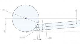
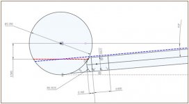
Screen Shot 2020-04-12 at 12.33.58 PM.jpeg
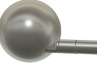
Closeup of tip-ball details.
 

Patrick Johnson

Fish of the Day
Silver Member
Your drawing of tip/ball contact shows that you might have a misconception about the miscue limit: it depends on your cue's angle of approach to the CB.

Your "horizontal miscue limit" is theoretically correct (red line halfway from center ball to edge), but the cue must be angled to hit that low (as you show), and with the cue angled like that the actual miscue limit (blue line) is also angled the same amount.

So your diagram shows a tip/ball contact that would almost certainly miscue.

Maybe it's just the drawing and not how you really picture the miscue limit...?

pj
chgo

rich.jpeg
 
Last edited:

iusedtoberich

AzB Silver Member
Silver Member
Your drawing of tip/ball contact shows that you might have a misconception about the miscue limit: it depends on your cue's angle of approach to the CB.

Your "horizontal miscue limit" is theoretically correct (red line halfway from center ball to edge), but our cue must be angled to hit that low (as you show), and with the cue angled like that the actual miscue limit (blue line) is also angled the same amount.

So your diagram shows a tip/ball contact that would almost certainly miscue.

Maybe it's just the drawing and not how you really picture the miscue limit...?

pj
chgo

View attachment 546077

Ok, thanks. To make sure I'm understanding you, the miscue limit should be measured perpendicular to the centerline of the stick, and account for the stick's angle? Go out 1/2 CB radius from there? Oh, and I'm also going to adjust it a hair above the miscue limit, as that would be more practical for a real player.
 

Patrick Johnson

Fish of the Day
Silver Member
Ok, thanks. To make sure I'm understanding you, the miscue limit should be measured perpendicular to the centerline of the stick, and account for the stick's angle?
Yes, and if you use a striped ball to show you the visible miscue limit (just about at the edges of a Centennial's stripe) for "target practice", be sure to tilt it the same way.

I'm also going to adjust it a hair above the miscue limit, as that would be more practical for a real player.
Good idea. Even if you want to try to hit exactly on the miscue limit the top of your shaft has to be slightly above that (as your drawing shows).

pj
chgo
 

iusedtoberich

AzB Silver Member
Silver Member
Ok I made the adjustment. 0.563” is the miscue limit. Do you think 0.500” is a reasonable offset for a good draw stroke by a real player?
 

iusedtoberich

AzB Silver Member
Silver Member
Screen Shot 2020-04-12 at 2.03.37 PM.jpeg
Adjustment made to model. Tip offset is now measured with respect to stick centerline angle.

Tip offset raised slightly from miscue limit of .563" to .500". This all now looks more realistic. Thanks Pat.
 

Patrick Johnson

Fish of the Day
Silver Member
Ok I made the adjustment. 0.563” is the miscue limit. Do you think 0.500” is a reasonable offset for a good draw stroke by a real player?
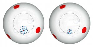
If you mean 0.500" to the actual tip/ball contact point (1/16" or so above max offset), that's safe enough - if your stroke is actually good enough to hit that consistently without straying much. Here's another drawing (I got a million of 'em) showing what I mean by that...

Nobody hits exactly where they want to every time, so we learn to aim at the center of our usual "shot group" so our tip doesn't stray too often outside the limit. The shot group on the left is of an OK player - the one on the right is of a better player.

pj
chgo

Shot Groups.jpg
 
Last edited:

iusedtoberich

AzB Silver Member
Silver Member
Screen Shot 2020-04-12 at 1.08.16 PM.jpeg

Design is too big for my printer (even if I orient it diagonally). I will have to cut it in half and print in two pieces.
 

iusedtoberich

AzB Silver Member
Silver Member
Screen Shot 2020-04-12 at 3.11.27 PM.jpeg
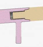
Here I cut it in two at the line to the right of the support.

Screen Shot 2020-04-12 at 3.11.44 PM.jpeg
I made it look like one of the ultra joint variations:)
 

iusedtoberich

AzB Silver Member
Silver Member
Screen Shot 2020-04-12 at 3.12.26 PM.jpeg
I had to add this webbing below the tip or the cue ball and the stick would separate. There is a good chance it won't be strong enough, and I'll have to make that webbing much larger. I'm hoping its ok as is, so it will look more realistic.

The grooves represent the start and stop of the ferrule. I can use them to help me paint or color with a sharpie the finished product.

Screen Shot 2020-04-12 at 3.12.52 PM.jpeg
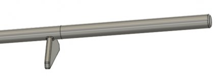
Here is a side view of the Rev 1 design. Bridge is very end of the stick, not the support.

Screen Shot 2020-04-12 at 3.13.18 PM.jpeg
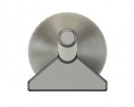
Here is the top view. (parallel to the slate)

Screen Shot 2020-04-12 at 3.26.07 PM.jpeg
Here is the rear view. (parallel to the slate).

I'm happy with it. Now to get it ready for the printer.
 

iusedtoberich

AzB Silver Member
Silver Member
Screen Shot 2020-04-12 at 3.52.01 PM.jpeg
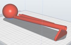
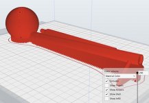
This is the printer software and how they will be arranged. Total time will be 5 hours. Material consumption will be 63 grams. Material cost is $1.26.

Screen Shot 2020-04-12 at 3.52.12 PM.jpeg
This shows all the support structure needed while printing. It will be flaked off when finished.

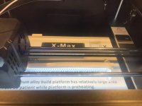
IMG_5876 (1).jpeg
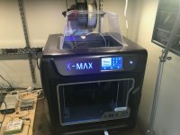
The printer.

IMG_5877.jpeg
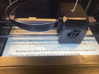
The first few layers.
 

Cron

AzB Silver Member
Silver Member
From the slicer, I'm going to assume it's an FDM printer and you're using PLA.

If you made the pedestal its own piece, that would drastically simplify things. What does your supports look like on the main body?

If you printed the body mostly rectangular, you could probably lower print times, decrease material usage and will decrease the chances of skipped steps cause 100% failure.

Did you test those threads first? It's hard telling, but it doesn't look like you added tolerances (typically, this is .5mm). Threads: https://www.youtube.com/watch?v=1nhcKn7Kt8w

Also, if you hollow out your own bodies you can control the infill slightly better as you can use overly meshes to change area and pattern. Definitely watch this simple mesh tutorial, meshes work for many things: https://www.youtube.com/watch?v=PUwf79wySUY
 

iusedtoberich

AzB Silver Member
Silver Member
From the slicer, I'm going to assume it's an FDM printer and you're using PLA.

If you made the pedestal its own piece, that would drastically simplify things. What does your supports look like on the main body?

If you printed the body mostly rectangular, you could probably lower print times, decrease material usage and will decrease the chances of skipped steps cause 100% failure.

Did you test those threads first? It's hard telling, but it doesn't look like you added tolerances (typically, this is .5mm). Threads: https://www.youtube.com/watch?v=1nhcKn7Kt8w

Also, if you hollow out your own bodies you can control the infill slightly better as you can use overly meshes to change area and pattern. Definitely watch this simple mesh tutorial, meshes work for many things: https://www.youtube.com/watch?v=PUwf79wySUY

1)Yes, FDM and PLA.
2) I want the ball, front half of stick, and pedestal, all printed as one piece. Its important to the function of this part that the tip is exactly at 6:00. I did not want to risk that by making them separate pieces. Good point though about separating them. It would definitely make the print simpler, but the design more complex. I could have a flat and other features to align them if I did separate them, but its good enough for a few hours of work:)

4) No, I did not test the threads, and as I did them I worried about the fit. The CAD I used has 3 classes of thread fit, and I chose the loosest. I wanted to make it even sloppier, but did not know how to do it in this software. (I'm used to using Creo). So, I'm crossing my fingers it will screw together.

I'll check out that YouTube link, thanks.
 

Patrick Johnson

Fish of the Day
Silver Member
View attachment 546100
This is the printer software and how they will be arranged. Total time will be 5 hours. Material consumption will be 63 grams. Material cost is $1.26.

View attachment 546101
This shows all the support structure needed while printing. It will be flaked off when finished.

View attachment 546102
The printer.

View attachment 546103
The first few layers.
Pretty cool stuff.

I'm holding out for the cranial implant that prints whatever I imagine out of air (you know it's coming).

pj
chgo
 

iusedtoberich

AzB Silver Member
Silver Member
If the shaft is connected rigidly to its support and everything is mounted to a rigid base they shouldn't separate unless made to...?

pj
chgo

I was originally going to make a base. But decided I wanted as little extra as possible, so it would look closest to the real thing. There are only 3 points of contact with the cloth. The base of the ball, and the two bottom portions of the rear support (well, that's a line....) So one point contact, and one line contact to the cloth.
 

Cron

AzB Silver Member
Silver Member
This was very helpful. Thank you. I'm impressed by fusion more and more. That press/pull command works so well.

I was also looking for a helical sweep (that's what its called in Creo), and this video showed a way to do that. Thank again.

Great. Hopefully you watch the mesh video as well. That by itself solves a lot of CAD work.

I'm not a mechanical engineer so I don't use any of these programs outside of 3D printing. I wish I was because I use 3D printing almost exclusively for mechanical things. Printing pool related objects became one of my 3D printing hobbies because of extensions and right now I doddle with printing "LD" shafts. In doing that, stress testing became a focus of mine, and while I wish I could say I went all the way down the rabbit hole with that, I just stopped. You just don't need a lot for shafts. However, the first video I watched (I've only seen about 10 total) was this one...

https://www.youtube.com/watch?v=q0YsC53mFvY

NOTE: The above video demonstrates meshes too. I guess if you were a CAD/CAM whiz you might find all that easy to do without meshes, but for me the meshes just seem easiest (and is probably almost always cleaner).

!! RANT related to 3D printing billiard parts !!

*IF* you _OWN_ a 3D printer, my belief (at 95% now) is that if you print _DISPOSABLE_ parts, you can print a shaft at least as good as anything you can buy. While I suspected I would eventually discover that I was still against it on the basis of recycling. However, with the advancements on recycling 3D materials becoming a hot topic, it's just a matter of time until it won't be a concern. So the ability to have the part in a matter of hours, tweaked how you like, the parts being repeatable and the low cost, this just becomes a "no brainer" _IF_ you own a 3D printer.

To end the specificity of pool shafts, right now I'm nearly certain that the butt should just be the lowest possible weight made of wood and the shaft should be made in 2 pieces. I'm going to rework my designs into 2 pieces because that way I will only have to print an object at most in 15" lengths (hopefully like 10"). I haven't done any stress testing yet on the effects of this, but it seems like the best approach as the shorter the printed piece, the faster and cheaper it becomes. I don't know, it's all a guess based on playing around at this point, so I'm very open to opinions.

Anyways, if you ever want a CoreXY printer or a printer of some fashion where the build surface doesn't move (or at least one axis is stationary), I _HIGHLY_ recommend building your own. I did _NOT_ do this and wish _VERY_ much that I did as the costs are way, way lower. The best part is that to learn how to get up and started in building your own printer isn't hard at all as you can just use assembly manuals from dozens of other printers to learn the concepts and mechanical goals.
 

iusedtoberich

AzB Silver Member
Silver Member
IMG_5881.jpeg
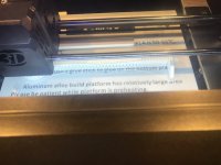
This was about one hour ago. You can see the rear of the shaft in the back is finished.

IMG_5883.jpeg
This is from now. 1.5 hours to go.
 
Top