Squirt. End Mass and Cue Flexibility.

LAMas

AzB Silver Member
Silver Member
The chart also shows about the same difference between 0 degrees and 180 degrees orientation, which should show no difference - so I'm thinking they're standard deviation differences (if I'm using that term correctly).

pj
chgo

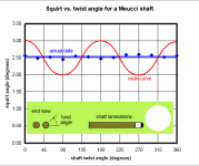
You and the chart from the empirical testing are correct. with the 35 layers oriented up and down and the black dot pointing up or zero or 180 degrees, the squirt was less than when the cue was rotated 90 or 270 degrees by about 5%. or more than Dave's aforementioned 1.5%.

Obviously the front end mass is the same regardless of orientation, but the stiffness is less at 0 and 90 degrees - almost insignificant so it seems except for a couple of scientists who wrote studies on this subject.

Cornerman mused that a shaft shaped like an "I" beam or a rectangular cross section would be lighter (less mass) than the ubiquitous round shape ergo less squirt and would yield similar results when rotated,

The ferrule would need some gusseting to be stable during several impacts.

Like Meucci, there could be a black dot atop the "I" beam like dotting the "I". :smile:


90 degrees.PNG
 

Corwyn_8

Energy Curmudgeon
Silver Member
You and the chart from the empirical testing are correct. with the 35 layers oriented up and down and the black dot pointing up or zero or 180 degrees, the squirt was less than when the cue was rotated 90 or 270 degrees by about 5%. or more than Dave's aforementioned 1.5%.

You might read the chart again, the squirt is lower for 90° and 180°, and higher for 0°, 270°, and 360°. Make sense of that if you can. To me it looks like experimental error. The difference is only 0.1° or so.

Error bars, DrDave?

Thank you kindly.
 

ENGLISH!

Banned
Silver Member
You and the chart from the empirical testing are correct. with the 35 layers oriented up and down and the black dot pointing up or zero or 180 degrees, the squirt was less than when the cue was rotated 90 or 270 degrees by about 5%. or more than Dave's aforementioned 1.5%.

Obviously the front end mass is the same regardless of orientation, but the stiffness is less at 0 and 90 degrees - almost insignificant so it seems except for a couple of scientists who wrote studies on this subject.

Cornerman mused that a shaft shaped like an "I" beam or a rectangular cross section would be lighter (less mass) than the ubiquitous round shape ergo less squirt and would yield similar results when rotated,

The ferrule would need some gusseting to be stable during several impacts.

Like Meucci, there could be a black dot atop the "I" beam like dotting the "I". :smile:


View attachment 410183

E,

For thought purposes only, forget the "I" beam, as the top & bottom have a stabilizing effect in that direction.

Just take the center piece out of the 35 laminations & then saw a slot down the middle of a slip on ferrule/tip or the like & attach it to the end.

Then hit the ball with the 'height' running up & down vs running sideways while hitting exactly on the equator of the ball with "it" perfectly level.

As you say the front end mass, or weight, is exactly the same.

Now what parameter has the most effect on squirt? "Front end mass" or FLEX?

It's the same shaped 'cue' with the same front end mass just in a different orientation regarding it's flex properties.

So...

the delivery method of the 'front end mass', even by the same piece of wood (plastic might be better), is different &

hence...

the effective front end mass would be vastly different.

I realize that this is not exactly how a round normal piece of wood would act given the taper, etc. It's just for visual & thought purposes.

The thing is that there are some that do not not like 'weak' whippy shafts. So, reducing the front end mass is probably the proper solution for them.

Then there are those that do not like the 'hollowness' of some of the LD shafts so for them adding flex may be the proper solution for them.

The thing is that up to now I do not think a shaft manufacturer has gone with a combination of both. They have gone in one direction or the other, but not both at the same time.

Golf Clubs were not too too long ago made of wood & forged steel. Then the casting process opened up a whole other realm of design capabilities.

Now club heads are made of multiple metals along with polymers. Tennis rackets were all wood, then steel, now fiberglass, graphite, & other materials. it's the same thing for baseball bats at the non Pro Level.

I don't think there is as much that can be done for pool & many good players have been quite capable of making the allowances for squirt & swerve but I can certainly see some young player coming out one day with a super high tech pool cue that is not made of wood or at least not entirely.

Back in the day who was thinking about reducing squirt but Bob Meucci? Today who but Bob Meucci is thinking about the effect that the butt of the cue might have & who else is using what I think is a patented plastic.

How about a hollow Plastic (liquid) tube with a cross diameter support with a slot cut out of the perimeter length at 90* to the diameter support but only on one(1) side?

Just food for thought.

Best 2 Ya & Stay Well, E.

PS there was a very fexibile fiberglass golf shaft that I think was called FiberSpeed. It was supposed to be able to 'recover' regardless of what speed the club was swung, form a weaker lady to a male pro. I think it worked but too many just did not like the whippy feel of it so it died a rather quick death.
 
Last edited:

dr_dave

Instructional Author
Gold Member
Silver Member
You might read the chart again, the squirt is lower for 90° and 180°, and higher for 0°, 270°, and 360°. Make sense of that if you can. To me it looks like experimental error. The difference is only 0.1° or so.

Error bars, DrDave?
Sorry, I no longer have the original data, so I can't offer error bars. The only information I have is what is in the squirt myth-busting article. Each data point was the average value over 5 shots (if my memory serves me right).

Regards,
Dave
 

LAMas

AzB Silver Member
Silver Member
You might read the chart again, the squirt is lower for 90° and 180°, and higher for 0°, 270°, and 360°. Make sense of that if you can. To me it looks like experimental error. The difference is only 0.1° or so.

Error bars, DrDave?

Thank you kindly.

You are right. I wrote what was logical.
Sorry,
Be well
 

Shawn Armstrong

AZB deceased - stopped posting 5/13/2022
Silver Member
I haven't had a chance to read through every post, so please forgive me if I ask a stupid question.

Does a tube react differently than a solid rod, when compressed the way a cue shaft is? I've always wondered if the hollowed out shafts worked due to being tubes instead of solid rods.

Thanks for any input!
 

dr_dave

Instructional Author
Gold Member
Silver Member
I haven't had a chance to read through every post, so please forgive me if I ask a stupid question.

Does a tube react differently than a solid rod, when compressed the way a cue shaft is? I've always wondered if the hollowed out shafts worked due to being tubes instead of solid rods.

Thanks for any input!
The hollow tube is lighter, which reduces endmass and CB deflection (squirt). The tube is also slightly more flexible (less stiff), which also helps reduce both endmass and CB deflection (squirt) a slight amount. The tube is also obviously not quite as strong.

For more info, see the squirt endmass and stiffness resource page.

Regards,
Dave
 

LAMas

AzB Silver Member
Silver Member
I haven't had a chance to read through every post, so please forgive me if I ask a stupid question.

Does a tube react differently than a solid rod, when compressed the way a cue shaft is? I've always wondered if the hollowed out shafts worked due to being tubes instead of solid rods.

Thanks for any input!

I also wondered why fishing poles are hollow instead of a thinner solid rod for the same bend radius and lateral force?
 

dr_dave

Instructional Author
Gold Member
Silver Member
I also wondered why fishing poles are hollow instead of a thinner solid rod for the same bend radius and lateral force?
A larger-diameter thin-wall tube is much lighter, while still providing adequate strength and stiffness).

Regards,
Dave
 

dr_dave

Instructional Author
Gold Member
Silver Member
Dr. Dave's measurement was with the cue supported back in the butt region, so most of the cue was flexing, whereas the calculation I did was based on a cantilever length of only six inches (because of the slow propagation of the shear wave). The "spring constant" is inversely proportional to the cube of the cantilever's length, so that's where the major difference comes in. Also, since Dr. Dave's measurement involved the tapered portion of the cue, differences arise from that as well, but would tend to bring the numbers closer together since that portion is much stiffer than the untapered section. The chance of these static measurements/calculations reflecting reality for the dynamic case is not all that great, imo.
Jim,

FYI, I did another set of stiffness measurements with only the 8 inches closest to the tip allowed to flex (which is closer to the situation occurring during tip contact). The measurements and new calculations are included in the latest version of TP B.19. This changed the bottom-line result from 1.6% to 14.1% (the percentage contribution of flex to squirt, compared to the endmass-momentum effect). As you point out, this is a big difference, but I think the conclusion is still accurate:

As has been shown with experiments dealing with adding and removing mass from the end of the shaft, endmass is much more important than shaft flex concerning how much CB deflection (squirt) a shaft creates (although, as pointed out on the endmass resource page, lateral or transverse stiffness does affect "effective endmass").

Thanks again for making me reconsider some of the assumptions and implications of the analysis.

Catch you later,
Dave

PS: I certainly agree with you that a static measurement doesn't perfectly model what is going on during the dynamic flexing of the cue during tip contact (nor is "effective endmass" a perfect model of the complex dynamic momentum transfer occurring during impact), but I am still confident with the "ball-park" results and conclusion of the analysis.
 

ENGLISH!

Banned
Silver Member
Big E,

Did you see that?

From 1.5% to 14.1% just because of a different method.

Now I wonder what if a shaft's end flexibility can be increased say with a long flexible ferrule &/or an hour glass taper at just the right location?

Maybe it can climb to 25%.

Then there is making the 'whole' shaft more flexible with a much longer then 'normal' pro parallel taper.

What do you think?

Best 2 Ya,
Rick
 
Last edited:

LAMas

AzB Silver Member
Silver Member
Big E,

Did you see that?

From 1.6% to 14.1%[/COLOR][/SIZE][/B] just because of a different method.

Now I wonder what if a shaft's end flexibility can be increased say with a long flexible ferrule &/or an hour glass taper at just the right location?

Maybe it can climb to 25%.

Then there is making the 'whole' shaft more flexible with a much longer then 'normal' pro parallel taper.

What do you think?

Best 2 Ya,
Rick

ENGLISH,
After 4,000+ hits we and others get a better answer to the question in this thread.
Thanks to intuition and tenacity, you and others helped to keep it alive and more real.:)

Thanks all and be well.
 

dr_dave

Instructional Author
Gold Member
Silver Member
Now I wonder what if a shaft's end flexibility can be increased say with a long flexible ferrule &/or an hour glass taper at just the right location?

Maybe it can climb to 25%.

Then there is making the 'whole' shaft more flexible with a much longer then 'normal' pro parallel taper.
Making a shaft more flexible (less stiff) would actually reduce the percentage contribution of flex force to CB deflection (squirt), not increase it.

And if the endmass is also reduced, the total amount of CB deflection (squirt) would also be lower.

Regards,
Dave
 

ENGLISH!

Banned
Silver Member
Making a shaft more flexible (less stiff) would actually reduce the percentage contribution of flex force to CB deflection (squirt), not increase it.

And if the endmass is also reduced, the total amount of CB deflection (squirt) would also be lower.

Regards,
Dave

Dave,

I think you misinterpreted my post to Lamas.

He seems to have understood it.

Best Wishes.
 

Jal

AzB Silver Member
Silver Member
FYI, I did another set of stiffness measurements with only the 8 inches closest to the tip allowed to flex (which is closer to the situation occurring during tip contact). The measurements and new calculations are included in the latest version of TP B.19. This changed the bottom-line result from 1.6% to 14.1% (the percentage contribution of flex to squirt, compared to the endmass-momentum effect). As you point out, this is a big difference, but I think the conclusion is still accurate:
Hi Dr. Dave,

Thanks for the additional work and info!

I'm in the middle of "refurbishing" the math (E-B beam treatment for the whole cue as well as the tip end) and as a matter of curiosity, looking forward to comparing your measurements to its predictions. (I may do a few myself.)

As has been shown with experiments dealing with adding and removing mass from the end of the shaft, endmass is much more important than shaft flex concerning how much CB deflection (squirt) a shaft creates (although, as pointed out on the endmass resource page, lateral or transverse stiffness does affect "effective endmass").
Forgive me. and perhaps as a petulant side note, I have to lodge a word of protest as to the notion that shaft flex/stiffness contributes anything to squirt apart from its role in creating (and delivering) endmass.

Jim
 

dr_dave

Instructional Author
Gold Member
Silver Member
Forgive me. and perhaps as a petulant side note, I have to lodge a word of protest as to the notion that shaft flex/stiffness contributes anything to squirt apart from its role in creating (and delivering) endmass.
Jim,

I know you don't agree with me on this, but I will try once more:

1.) Shaft endmass can be increased significantly by adding mass close to the tip (e.g., by using a heavier tip or ferrule, by inserting something heavy but not stiff into a cored-out shaft, or by physically adding external mass to the tip end of the shaft). This has been clearly demonstrated with numerous experiments by me, Mike Page, and others. In these cases, the endmass is increased dramatically with no increase in shaft stiffness.

2.) Removing endmass from a shaft without significantly changing the stiffness of the shaft (e.g., by using a lighter ferrule and/or by drilling out the core of the shaft end), can significantly reduce the amount of effective endmass and squirt. This has also been demonstrated with the design of Predator shafts. Drilling out the core does not have a huge effect on shaft-end stiffness, but it does dramatically reduce endmass and squirt (as does the lighter ferrule).

3.) As my TP B.19 analysis shows, the total sideways force acting between the tip and CB is due to two physical effects. Part of the force contributes impulse which imparts momentum to the endmass of the shaft. The other part of the force (much smaller) is required to flex the shaft. The end of the shaft effectively looks like a mass supported by a spring. Think of a simple diagram of a linear spring-mass system with an applied force pushing on a mass supported by a spring. Some of the force applied to the mass goes into accelerating the mass (imparting momentum), and some goes into compressing the spring (F_total = F_applied - kx = ma). The resultant force experienced by the mass is not the force applied to the mass (F_applied); rather, it is the amount of excess force not being resisted by the spring (F_applied - kx). I think the answer to the question "In your TP B.19 analysis, how does the flex-force impulse relate to the sideways impulse between the tip and CB?" near the bottom of the squirt endmass and stiffness effects resource page shows how the same logic applies to the squirt-endmass-stiffness problem. The difference between the shaft-endmass-lateral-stiffness problem and the simple linear-spring-mass problem is that the total endmass of the shaft depends on shaft stiffness (in addition to the weight of the tip, ferrule, and anything else on or in the end of the shaft), but the spring force is still there.

Sorry Jim, but that's the best I can do. If these 3 things don't convince you, then we will need to agree to disagree on this one.

Best regards,
Dave
 
Last edited:

Jal

AzB Silver Member
Silver Member
Jim,

I know you don't agree with me on this, but I will try once more:

1.) Shaft endmass can be increased significantly by adding mass close to the tip (e.g., by using a heavier tip or ferrule, by inserting something heavy but not stiff into a cored-out shaft, or by physically adding external mass to the tip end of the shaft). This has been clearly demonstrated with numerous experiments by me, Mike Page, and others. In these cases, the endmass is increased dramatically with no increase in shaft stiffness.

2.) Removing endmass from a shaft without significantly changing the stiffness of the shaft (e.g., by using a lighter ferrule and/or by drilling out the core of the shaft end), can significantly reduce the amount of effective endmass and squirt. This has also been demonstrated with the design of Predator shafts. Drilling out the core does not have a huge effect on shaft-end stiffness, but it does dramatically reduce endmass and squirt (as does the lighter ferrule).

3.) As my TP B.19 analysis shows, the total sideways force acting between the tip and CB is due to two physical effects. Part of the force contributes impulse which imparts momentum to the endmass of the shaft. The other part of the force (much smaller) is required to flex the shaft. The end of the shaft effectively looks like a mass supported by a spring. Think of a simple diagram of a linear spring-mass system with an applied force pushing on a mass supported by a spring. Some of the force applied to the mass goes into accelerating the mass (imparting momentum), and some goes into compressing the spring (F_total = F_applied - kx = ma). The resultant force experienced by the mass is not the force applied to the mass (F_applied); rather, it is the amount of excess force not being resisted by the spring (F_applied - kx). I think the answer to the question "In your TP B.19 analysis, how does the flex-force impulse relate to the sideways impulse between the tip and CB?" near the bottom of the squirt endmass and stiffness effects resource page shows how the same logic applies to the squirt-endmass-stiffness problem. The difference between the shaft-endmass-lateral-stiffness problem and the simple linear-spring-mass problem is that the total endmass of the shaft depends on shaft stiffness (in addition to the weight of the tip, ferrule, and anything else on or in the end of the shaft), but the spring force is still there.

Sorry Jim, but that's the best I can do. If these 3 things don't convince you, then we will need to agree to disagree on this one.
Dr. Dave,

Thanks for taking the time to explain.

I'm sure of two things. One is that given the fact that the forces involved are all internal to the cue-cueball system, lateral momentum must be conserved during every moment of the collision (i.e., = 0 for a straight stroke). Second is that you know that (and know it far better than me, given everything).

If you can construct a scenario where a force is acting on the cueball that is not acting equally and opposite on the endmass, I think, well, I won't know what to think. It's true that a flex force does act on the cueball, but in acting equally and opposite on the endmass, it acts in the opposite direction of what our intuition suggests, which would be to push the endmass in the same direction as the cueball.

If this is the situation described by your example:

]///////////(mass 1)<----- Force----->(mass 2)

then the force is pushing on the wall behind the spring besides compressing it. Without the wall (the support), there is no compression. So the analogous "endmass" here is mass1 plus the wall plus whatever it's attached to. If the momentum of the combined system: m2, m1, wall.. was zero to begin with, it's zero throughout the interaction. That is to say, whatever force acts against m2, acts equally (and oppositely) on m1-wall... There is no force acting on m2 that's not acting on m1-wall... It's surely true, as you say, that the force on m1 is less than that on m1-wall.. But m1 isn't the entire "endmass," by my argument. Obviously, with a cue's endmass, there is no wall, just m1:

(mass 1)///////////<----- Force----->(mass 2)

in which case m1 does feel whatever m2 feels (but opposite).

That's probably my best shot too, so we just may have to agree to disagree. (It was you and Patrick that convinced me that it was all endmass, so to speak. So I think one thing we can agree on for sure, is that we must be trapped in some sort of diabolical space-time loop!)

Jim
 
Last edited:
Top