CNC Inlay Machine Design

Thomas Wayne

AzB Silver Member
Silver Member
Just pointing out that almost any time a cuemaker independently comes up with a process (or end result) and thinks it's something that "hasn't been achieved until now"... he's probably wrong. There had been plenty of very innovative techniques devised before I ever started building cues, and plenty more afterwards.

I'm always interested in seeing the next genuinely new thing, but rarely does it turn out to be so. Cuemakers are always reinventing the wheel - which is fine - but if what they've come up with is not truly "new" then it seems reasonable to give credit where credit is due.

TW
 

RBC

Deceased
Just pointing out that almost any time a cuemaker independently comes up with a process (or end result) and thinks it's something that "hasn't been achieved until now"... he's probably wrong. There had been plenty of very innovative techniques devised before I ever started building cues, and plenty more afterwards.

I'm always interested in seeing the next genuinely new thing, but rarely does it turn out to be so. Cuemakers are always reinventing the wheel - which is fine - but if what they've come up with is not truly "new" then it seems reasonable to give credit where credit is due.

TW

I understand Thomas, it's all good!

I'm familiar with many ways of making sharp inlays. Some of them may even be methods that you've created. But I've not found anyone that is doing anything remotely similar to what we're doing.

Of course, I'm really talking about methodology, not necessarily the final outcome. Certainly there are many ways to come up with sharp inlays. The thing is that I've only seen them on higher end custom cues. In the production world it's all the old round end stuff. Well, I can honestly say that our method is no more difficlut than the old round end stuff, but yields completely different results.

As I've often said, you truly are a Master at the art of the cue. We hope to earn similar accolades in the production cue world. Don't know if we'll ever get there, but we will sure give our best shot.


Thanks for playing!

Royce
 
Last edited:

GBCues

Damn, still .002 TIR!
Gold Member
Silver Member
Hey Guys,
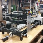
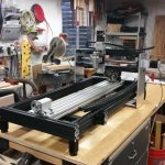
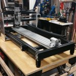
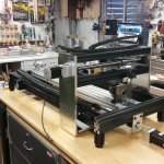
It's been 3 weeks since my last update, so I thought I would show my progress so far. The mechanicals are pretty much done - there is still leveling to do, but at this point everything moves easily and without binding. Thanks again to all who had design suggestions last time. It was pretty easy to go to a single long-axis drive. Also I added the bottom stiffening plate. - Thanks Jake and Royce and Steve. My apologies if I left anyone out - it is not intentional.
Now it's on to the electronics. I have a new Gecko G540, an ethernet BOB, 18-volt relay, some variable resistor 9-pin shells for the cables, a 5-volt PS, and a pendant all from Soigeneris.com - IMHO they have a great collection of CNC accessories and parts.
And from previous purchases, I have 48-volt power supply for the controller and speed control for the spindle, etc. The electronics build out will keep me busy for a while.
And I was able to get a copy of BobCAD V25 with training videos on eBay - I'll finalize the license transfer with BobCAD this coming week, and then it's even MORE learning to do. Apologies to Jim, I couldn't resist taking a chance on this eBay deal.
Thanks again to all who have contributed to the improvements in my original design. It's been a year in the making, but I think it's looking good! :smile:
Gary
 

Attachments

  • July 27, 2014 #1.jpg
    July 27, 2014 #1.jpg
    92.2 KB · Views: 322
  • July 27, 2014 #2.jpg
    July 27, 2014 #2.jpg
    94.9 KB · Views: 321
  • July 27, 2014 #3.jpg
    July 27, 2014 #3.jpg
    94.1 KB · Views: 402
  • July 27, 2014 #4.jpg
    July 27, 2014 #4.jpg
    94.5 KB · Views: 315

Mc2

AzB Silver Member
Silver Member
No apologies needed. Hope it was a good deal. Did you get the smooth stepper? I like those. Things to add are a camera and home switches.

Looks good, Jim
 

danieldakota53

AzB Silver Member
Silver Member
I like it, are you going to add more 4th axis tables as you go for dedicated tapering, shaft turning, ring making, ect? One of the better designs on the market for cue maker's I think is the router table design. Very versatile and end to end inlaying capacity. And expandable when needed. Great design and follow through to you and continued success.
 

GBCues

Damn, still .002 TIR!
Gold Member
Silver Member
No apologies needed. Hope it was a good deal. Did you get the smooth stepper? I like those. Things to add are a camera and home switches.

Looks good, Jim

Jim,
I got the ethernet smooth-stepper - everything I read about them in general said they are superior to a parallel port. I will be running this controller on a Windows7 64-bit machine which is another reason to go with a smooth stepper, whether it be USB or ethernet.
I have optical switches for my home switches.
I keep hearing about the camera thing, and I need to investigate that further as I'm still unclear how to use one.
Thanks very much for your help in the past on the optical switches and other CNC related topics.
:thumbup:
Gary
 

GBCues

Damn, still .002 TIR!
Gold Member
Silver Member
I like it, are you going to add more 4th axis tables as you go for dedicated tapering, shaft turning, ring making, ect? One of the better designs on the market for cue maker's I think is the router table design. Very versatile and end to end inlaying capacity. And expandable when needed. Great design and follow through to you and continued success.
Daniel,
Thanks for the kind words. Yes, down the road I will replace the fixed headstock with a true 4th axis CNC headstock - LGSM brought that to my attention. I have been using a 2-axis taper attachment to my lathe for tapering for a couple of years. But moving up to 3-axis pretty much required going to CAD/CAM. I figured one more axis at a time is a big enough bite to chew off.
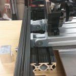
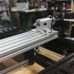
Another feature that may not be obvious, but was the suggestion of yet another cuemaker here was to hinge the table so that it can be tilted up like a sine plate. You can just make out the hinges behind the headstock.
Edit: I added a couple of pictures to show the sine plate - the lift is exagerated here, but makes it obvious.
Thanks again,
Gary
 

Attachments

  • 20140728_190315.jpg
    20140728_190315.jpg
    82.3 KB · Views: 286
  • 20140728_190332.jpg
    20140728_190332.jpg
    85.3 KB · Views: 288
Last edited:

Mc2

AzB Silver Member
Silver Member
Jim,
I got the ethernet smooth-stepper - everything I read about them in general said they are superior to a parallel port. I will be running this controller on a Windows7 64-bit machine which is another reason to go with a smooth stepper, whether it be USB or ethernet.
I have optical switches for my home switches.
I keep hearing about the camera thing, and I need to investigate that further as I'm still unclear how to use one.
Thanks very much for your help in the past on the optical switches and other CNC related topics.
:thumbup:
Gary

Gary, the camera is very useful for a few things. I have an offset in Mach to move over the distance between my camera and the spindle. This is easy to determine as you drill a small hole into a scrap piece. With your DROs zeroed out jog until your camera is centered over the hole. Record that distance and use it for your camera shift. Mach 3 has a plug in that when used with a usb camera displays a window with cross hairs. This camera is useful to find center of the cue. To make sure that the cue is straight between your rotary table and tail-stock. And to find centers between two items. If you find with the camera the location you want X and Y zero, then shift to spindle and set X and Y to zero. I also use the camera to verify that when I re-index a cue or part it is on center. I will pre-drill a marker hole somewhere at a known distance that I can check next time I run a program on that item. I can stack up multiple parts with confidence that I am lined up on the part correctly.

As far as information on getting a camera, hold on a bit. There is a guy that used to sell them on e-bay from Europe. He is working on a new one to sell and has sent us a sample. I have not received it yet but will let you know how well it works and how to order one. Should run around $200 but worth while.

Jim.
 

TomHay

Best Tips For Less
Gold Member
Silver Member
Gary, the camera is very useful for a few things. I have an offset in Mach to move over the distance between my camera and the spindle. This is easy to determine as you drill a small hole into a scrap piece. With your DROs zeroed out jog until your camera is centered over the hole. Record that distance and use it for your camera shift. Mach 3 has a plug in that when used with a usb camera displays a window with cross hairs. This camera is useful to find center of the cue. To make sure that the cue is straight between your rotary table and tail-stock. And to find centers between two items. If you find with the camera the location you want X and Y zero, then shift to spindle and set X and Y to zero. I also use the camera to verify that when I re-index a cue or part it is on center. I will pre-drill a marker hole somewhere at a known distance that I can check next time I run a program on that item. I can stack up multiple parts with confidence that I am lined up on the part correctly.

As far as information on getting a camera, hold on a bit. There is a guy that used to sell them on e-bay from Europe. He is working on a new one to sell and has sent us a sample. I have not received it yet but will let you know how well it works and how to order one. Should run around $200 but worth while.

Jim.

Jim, fantastic wording on the camera. Today I think its a must have.

I wanted to say how nice it is of Gary to go step by step with photos of his project, its what makes this forum great.
 

LGSM3

Jake<built cues for fun
Silver Member
nice job Gary. Like the sine plate integration. I actually have one of the cameras that Jim is referring too and wont be using it...holler if your interested.

I've got a machine similar to yours underway but don't have the time to mess with it so I get to live vicariously through guys like you....keep up the good work
 

Mc2

AzB Silver Member
Silver Member
Gary, I have a similar tilt bed on my cnc. If you raise the hinge end up a bit then you will be able to tilt with taper going either direction. A word of causation , when you apply pressure with tail stock the bed will bow and the center of the cue will bow upwards. Mine is as much as .010". I added a stiffener on the bottom to minimize this however it is still there. Oh and I should mention that I used a Taig mill attachment for their lathe to move my bed end up and below center of other end.

Jim.
 

GBCues

Damn, still .002 TIR!
Gold Member
Silver Member
Hey Guys,
Thanks for discussing the camera a bit more. I've been poking around myself and received a USB endoscope camera today that is supposed to resolve out around 1024 x 768 and higher. Thanks to my real job, I haven't even had a chance to plug it in and test it. I will in the next few days and post more details.
Jim, thanks for the Mach3 info. I'll look into the plug-in. Also, the Taig mill attachment is a good idea for adjusting the sine table - I've got one that rarely gets used and I hadn't finalized that piece. I was going to simply use screws, but this idea is much more precise.
:thumbup:
Gary
 
Last edited:

BigDon

DESi Customs
Silver Member
Gary, it's looking like it is really coming along. Looks good!

Jim, I have been collecting parts and designing a cnc myself. Did you have to hinge the other end as well? How are you dealing with the bed wanting to swing in an arc at the lifted end when raised or lowered? Hope I am explaining myself correctly.

Thanks!
 

Mc2

AzB Silver Member
Silver Member
Gary, it's looking like it is really coming along. Looks good!

Jim, I have been collecting parts and designing a cnc myself. Did you have to hinge the other end as well? How are you dealing with the bed wanting to swing in an arc at the lifted end when raised or lowered? Hope I am explaining myself correctly.

Thanks!

Don, you are correct, I am hinged on both sides. You will want that to swing easily with no play. I find center on my cue at the chuck end and then check center on the tail stock end. I will adjust my tail stock end to match the chuck center. After that I sweep the length of my part for flatness. This is where you will notice the bow in the center. Once I am flat I will double check the center on the tail stock. I am rarely off at this point.

Jim.
 

LGSM3

Jake<built cues for fun
Silver Member
i cant see where that extrusion is going to get alot of sag "anymore than it already has when its just sitting there without a cue in it" A quick and easy fix would be to just bolt a 3/8" plate on edge in the side t-slot. Maybe just lock all the bolts down hardcore when you sweep it true.
 

GBCues

Damn, still .002 TIR!
Gold Member
Silver Member
What about filling the bed with concrete like taig does. That would surly make it stronger.

Joe,
In the last picture I saw of your CNC rig, I think it was a T-Slot bed as well - are you hinting that you filled it with concrete?
Gary
 

JBCustomCues

AzB Silver Member
Silver Member
Joe,
In the last picture I saw of your CNC rig, I think it was a T-Slot bed as well - are you hinting that you filled it with concrete?
Gary


No. My machine has supports every 12 inches. Yours is a single piece of extrusion that you are using as a sine table as well with zero support. So it was just a suggestion to make it more rigid.
 

conetip

AzB Silver Member
Silver Member
Putting adti on things and then pushing or leaning on it will tell you a lot about the rigidity of what you have. Having raised blocks or pads , and then tension wires, is a light weight way of adding rigidity while minimising weight. That is why they used them in early planes.
Making things heavy does not always mean it will be straight or have an increase in flexural modulus.
I am not a fan of mixing steel with ali parts, mainly due to the bi metal strip effect with temperature change.
Pre bending, or pre tensioned parts is what they do on truck trailer beds to help them become flat with the load applied. Having some form of compensation for weight is often a very useful when wanting to make flat or straight somethings. The more accurate you are trying to achieve the more involved things become that is for sure.
That is why having a work shop at a fairly constant temp helps out so much.
I was working on a job last week, and a temp change of the shop to the measuring room ment that the change in dimension was greater than the tolerance of the part.
Neil
Neil
 
Top