help with wiring a reversible motor

hardknox222

AzB Silver Member
Silver Member
I got a Marathon Motor 115v 60 HZ 1725 RPM 1/4 HP reversible motor

http://www.peck-polymers.com/store/Category.asp?Cguid={20F3B1BA-14CD-4256-8B34-084126FEF6B3}&Category=Taig%3AAccessory+Lathe

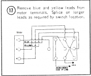
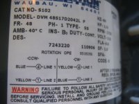
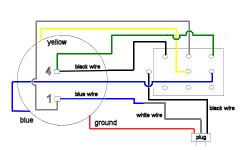
The wiring diagram on the motor shows:

CW
Yellow - 1 = Line 1
Blue - 4 = Line 2

CCW
Blue - 1 = Line 1
Yellow - 4 = Line 2

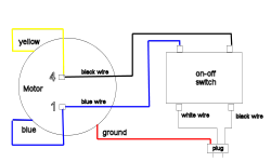
I've got a Carlingswitch HM254-73 toggle switch with 9 connections. How do I make the connection from the motor to the switch?

Thanks.
 

WilleeCue

The Barefoot Cuemaker
Silver Member
What you need is a heavy duty double throw, double pole switch like the ones they sell at the auto stores.

There are 6 contacts on the bottom.

The middle two are line 1 and line 2 (AC power in).

The yellow1 and blue-4 on the two contacts at one end of the switch
and the blue-1 and yellow-4 on the two contacts on the other end of the switch.

If you take a good photo of the contacts on the switch you now have I might be able to help you hook that one up also.
 

WilleeCue

The Barefoot Cuemaker
Silver Member
Deleted ............... Wrong Information ................
 
Last edited:

hardknox222

AzB Silver Member
Silver Member
The switch came with a 3 page manual with several different diagrams but the closest I can find to my setup is attached. So from what you are saying, row 2 would be line 1 and row 3 will be line 2, correct? So what's row 1 used for? This diagram is also using 1, 2 and 4 on the motor besides the blue and yellow connections. If I switch the 2 and 1 on the motor from the diagram, will that work?

I am just confused. :confused:
 

Attachments

  • diagram.png
    diagram.png
    31.8 KB · Views: 5,852
Last edited:

WilleeCue

The Barefoot Cuemaker
Silver Member
Wow ... now I am confused.
I thought one pair of wires ran the motor in one direction and the other pair ran it in the other direction.

Looking at the schematic that is not the case.

The motor drawing is confusing as it shows five wires from the motor but your first post indicated there were only four wires.
It would have been nice if the drawing would show the colors of all the wires.

Not enough information ... Got me stumped.
 
Last edited:

dchristal

Senior
Silver Member
Ok, I'll take a stab. It's a 3PDT switch meaning that it can connect three wires on-off-on.

The first on-off-on pole is used to switch the black (power) wire from the motor to the hot(usually black or brown) from your power source.

If the motor has a white wire, that's neutral and should be directly connected to the white(sometimes blue) power wire.

If you're not absolutely clear about this part, you need to get some help.

The remaining two poles on the switch should be wired to allow reversing the blue & yellow wires. blue to blue and yellow to yellow causes the motor to rotate one direction. blue to yellow and yellow to blue causes the motor to reverse. The right side of your diagram indicates how to do this.

Above all, be safe and don't blame me if this doesn't work. Just trying to help.
 

hardknox222

AzB Silver Member
Silver Member
Here's my current setup. The motor came pre-wired with only an On-off switch. I've attached pictures so you guys can clearly see the current wiring and what I would like to do.

On the motor, I have "yellow" connected to "4" and "blue" connected to "1". It also has a "blue wire" that connects to line 1 of the switch and a "black wire" connected to line 2. There is also a "red wire" for ground.

On the power source, I have a "white wire" connect to line 1 and a "black wire" connected to line2 on the switch and a ground wire which connects to the ground wire on the motor.

This setup allows the motor to rotate only in one direction. If I want to reverse it, I just switch the yellow and blue wires on the motor and it's not too big of a deal as it takes me just a few seconds to do.

What I want to do now is to use my on-off-switch with 9 connectors but I don't know how the existing wires on my motor and power source get connected to this new switch. Also, why is one connector facing outwards on this switch?
 

Attachments

  • wiring.png
    wiring.png
    14.6 KB · Views: 5,867
  • motor_wires.jpg
    motor_wires.jpg
    58 KB · Views: 5,385
  • switch.jpg
    switch.jpg
    39.7 KB · Views: 5,018
  • diagram.jpg
    diagram.jpg
    52.1 KB · Views: 5,294

dchristal

Senior
Silver Member
1 2 3
| \ /
4 5 6
| / \
7 8 9

Disconnect the white and blue wires from the switch and splice them.
Connect the black power wire to 4 on the new switch.
Connect the black motor wire to 1 on the new switch.
Connect the yellow wire to pin 5 on the new switch.
Connect the blue wire to pin 6 of the new switch.
Run a wire from pin 2 of the new switch to the spot on the motor where the blue wire was connected.
Run a wire from pin 3 of the new switch to the spot on the motor where the yellow wire was connected.

Should work.
 

hardknox222

AzB Silver Member
Silver Member
dchristal said:
1 2 3
| \ /
4 5 6
| / \
7 8 9

Disconnect the white and blue wires from the switch and splice them.
Connect the black power wire to 4 on the new switch.
Connect the black motor wire to 1 on the new switch.
Connect the yellow wire to pin 5 on the new switch.
Connect the blue wire to pin 6 of the new switch.
Run a wire from pin 2 of the new switch to the spot on the motor where the blue wire was connected.
Run a wire from pin 3 of the new switch to the spot on the motor where the yellow wire was connected.

Should work.

Thanks. So the last 3 contacts will be empty? Is my diagram below correct?
 

Attachments

  • wiring.png
    wiring.png
    13.1 KB · Views: 23,897

cueman

AzB Gold Member
Gold Member
Silver Member
dchristal said:
1 2 3
| \ /
4 5 6
| / \
7 8 9

Disconnect the white and blue wires from the switch and splice them.
Connect the black power wire to 4 on the new switch.
Connect the black motor wire to 1 on the new switch.
Connect the yellow wire to pin 5 on the new switch.
Connect the blue wire to pin 6 of the new switch.
Run a wire from pin 2 of the new switch to the spot on the motor where the blue wire was connected.
Run a wire from pin 3 of the new switch to the spot on the motor where the yellow wire was connected.

Should work.
If that switch has the built in jumpers your method will be correct. On a normal 3PDT switch I have to use short jumper wires to do exactly what you showed. I didn't even know they made a switch with built in cross-over connections. We all live and learn. I would add one item here. You will still need to hook up the ground (white wire in most cases) from your power cord to the same bottom position it was hooked to on the motor.
 
Last edited:

dchristal

Senior
Silver Member
Yes, the last three contacts will be empty, but be sure that the screws are tight, as they really are connected (and used) via the metal strips that I see in switch.jpg.
 

KJ Cues

Pro Cue Builder & Repair
Silver Member
If all you want to do is swap the blue & yellow, I think you can do that with a 2p2t switch and a set of Chris's jumpers. Why even mess with the other wires?
 

hardknox222

AzB Silver Member
Silver Member
KJ Cues said:
If all you want to do is swap the blue & yellow, I think you can do that with a 2p2t switch and a set of Chris's jumpers. Why even mess with the other wires?

No reason. I just have the switch and I would like to use it.

Thanks dchristal for the instructions and cueman for the verification. I will try to do the connections tonight.
 

cueman

AzB Gold Member
Gold Member
Silver Member
KJ Cues said:
If all you want to do is swap the blue & yellow, I think you can do that with a 2p2t switch and a set of Chris's jumpers. Why even mess with the other wires?
It is because you also need a line just for the hot wire. A 2PDT switch would indeed revesre the blue and yellow, but you also need a pole to turn teh motor on and off. I have recetly started wiring my motors with two switches. One 2PDT (on/on) type and a single off/on switch. This eliminates having to replace the more expensive switch when one pole goes out. Since it is the on/off switch that gets uses most it will be the cheaper switch that goes out and the easiest one to purchase locally.
 
Top