Fun. Love the sin sweepIt’s alive.
Cue Spinner

You are using an out of date browser. It may not display this or other websites correctly.
You should upgrade or use an alternative browser.
You should upgrade or use an alternative browser.
Homemade Tip Replacement Lathe
- Thread starter nataddrho
- Start date
DeeDeeCues
Well-known member
A dial caliper or a veneer is for measuring something, it has 2 contact points. A dial indicator has a single contact point and is most commonly used for measuring runout. It can be used for dimensional measurements but it usually requires a fixture of known dimensions.
Dial caliper.
View attachment 917139
A veneer is for teeth or wood working.
A vernier is a type of scale.

View attachment 917147
Dial Up Modem....

I purchased parts to make a homemade tip changing lathe. There are a couple other threads similar to this but their picture links are broken.
I already made a speed controller out of spare parts that I had, which generates 270 oz-in (1.4 ft-lbs) of torque from 100 to 1000 RPM... I think this is enough for tip shaping work...
View attachment 912839 View attachment 912840
I am planning on directly coupling the motor to a chuck. I'll use cloth or electrical tape on the joint end of the shaft. The tip end of the shaft will fit though a pillow bearing with collets. My amazon order is under $101 including shipping.
View attachment 912838
View attachment 912841
The bearings have set screws in them which I hope will allow me to adjust them using a dial caliper (which I don't own yet). I just plan on using a block of wood with a razor blade screwed into the top as a tool, or maybe just a block of sand paper.
View attachment 912842
Is there anything I am missing?
Im late to this thread but i use those same block bearings for my low rpm finishing lathe, that spins slowly while epoxy hardens.
It looks like your design is good enough, but if you wanted to improve runout you could use a belt and pulley to drive a mandrel that’s fixed in one of your bearings. That would require making a mandrel with a pin that matches your shafts, which would exceed your budget if you don’t have tooling already.
DeeDeeCues
Well-known member
Im late to this thread but i use those same block bearings for my low rpm finishing lathe, that spins slowly while epoxy hardens.
It looks like your design is good enough, but if you wanted to improve runout you could use a belt and pulley to drive a mandrel that’s fixed in one of your bearings. That would require making a mandrel with a pin that matches your shafts, which would exceed your budget if you don’t have tooling already.
The runout appears to be because he isn't using a bearing on his drive side. It appears he has his chuck mounted directly to a spider coupling.
The runout appears to be because he isn't using a bearing on his drive side. It appears he has his chuck mounted directly to a spider coupling.
I missed that. Amazon sells these bearings in packs of 2 so I assumed he had one on both ends of his shaft.
DeeDeeCues
Well-known member
I missed that. Amazon sells these bearings in packs of 2 so I assumed he had one on both ends of his shaft.
Yeah, I can't figure this one out. The OP seems to have some knowledge, but this would be a perfect project to show what not to do for a lathe spinner. Several people have already commented on how great this looks, so maybe they are taken in by something.
In reality, this is no better, and possibly worse, than one of those spinners that use an electric drill strapped to a board with a bearing on one end. The drill ones at least have a rigid drive that isn't letting the joint end run anywhere it wants.
I'm not trying to be mean, but for anyone who doesn't know, the coupler on the motor is a three-part coupler that is made to be slightly flexible to account for any misalignment between a rigidly mounted motor and the driven end of a rigidly mounted shaft (shaft in the mechanical sense, not cue shaft). These couplers fit together by friction. When they are allowed to run like this, they can walk apart. If that happens while changing a tip, the shaft and chuck (and part of the coupler) will be sent flying.
I encourage people who want to build something like this to see some advice from someone who has worked in machine design.
Engineering is the art of trade-offs. There are many versions of the constraint triangle, but here is a common one:

You can only have two of the three corners of the triangle. From your comment above you aren't willing to sacrifice High Quality, so your only options are to either spend more money building something with higher performance, or taking a long time to optimize something that still has high performance.
For this project I am deliberately picking Low Cost and Done Quickly, so I must live with Low Quality as a constraint. Now that I know this, what is the magnitude of my Low Quality?
I know that a flexible coupling will have run-out, and from the video it looks to be about 1/8". The pillow bearing is mounted about an inch from the tip. Using the rule of small angles, the run-out at the tip is approximately 1/8" x 1"/27" = 0.005" or 5 mils. Lets say the bearing has some additional slop, so that the tip deviates around 10 mil while spinning.
This is unacceptable work-piece run-out for a cutting tool on a carriage.
However, the 10 mil is absorbed by the fact that I am using a wooden block wrapped in sand paper as my tool, and holding it with my hands, which is even worse precision than the runout
EDIT: This is also one of the reasons machine shop guys complain that engineering doesn't know what they hell they are doing, and that this will never work well. There are usually layers of management and finances demanding all three corners of the triangle at once, and engineers need to cut corners to keep schedules working.
You can only have two of the three corners of the triangle. From your comment above you aren't willing to sacrifice High Quality, so your only options are to either spend more money building something with higher performance, or taking a long time to optimize something that still has high performance.
For this project I am deliberately picking Low Cost and Done Quickly, so I must live with Low Quality as a constraint. Now that I know this, what is the magnitude of my Low Quality?
I know that a flexible coupling will have run-out, and from the video it looks to be about 1/8". The pillow bearing is mounted about an inch from the tip. Using the rule of small angles, the run-out at the tip is approximately 1/8" x 1"/27" = 0.005" or 5 mils. Lets say the bearing has some additional slop, so that the tip deviates around 10 mil while spinning.
This is unacceptable work-piece run-out for a cutting tool on a carriage.
However, the 10 mil is absorbed by the fact that I am using a wooden block wrapped in sand paper as my tool, and holding it with my hands, which is even worse precision than the runout
- Compared to ISO 9001 and expected machine shop quality standards, this won't pass.
- Compared to changing a tip completely by hand like in Dr. Dave's videos, it is an improvement.
EDIT: This is also one of the reasons machine shop guys complain that engineering doesn't know what they hell they are doing, and that this will never work well. There are usually layers of management and finances demanding all three corners of the triangle at once, and engineers need to cut corners to keep schedules working.
Last edited:
Results:
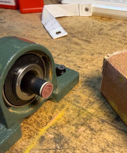
Removing old tip
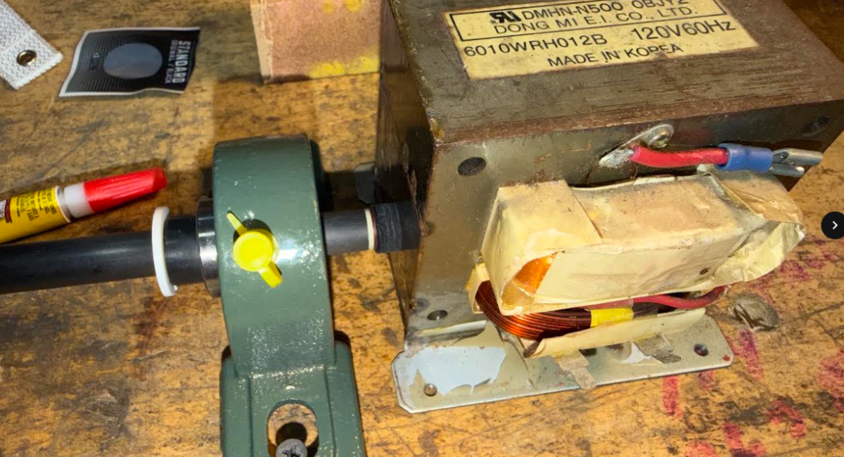
Gluing on new tip and holding in place while cyanoacrylate sets:
New tip:
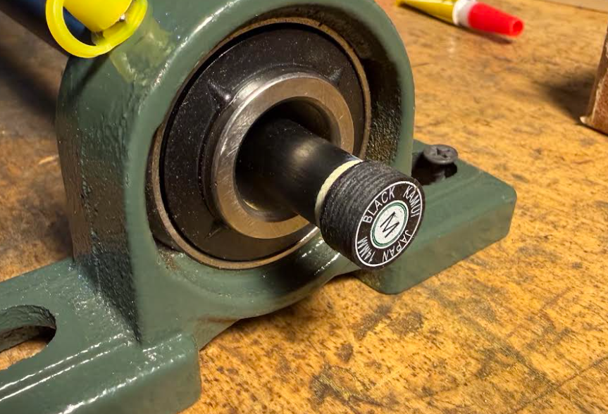
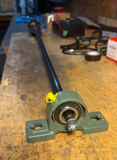
Sanding, shaping and burnishing tip: (60 grit, 100 grit, 330 grit and leather)
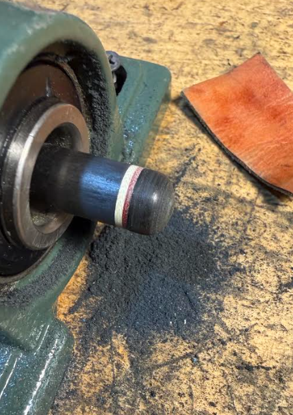
Done:
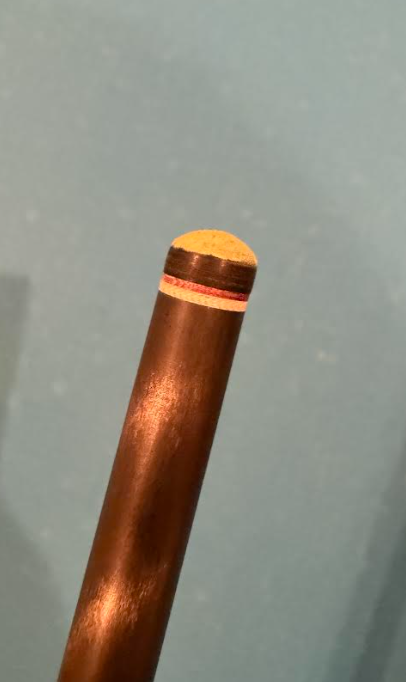
If you look closely, the sides aren't perfectly flush, but it levels out quickly as I reshape any mushrooming as the tip breaks in.
The whole process took 20 minutes, and was much better than mailing/traveling/downtime to pay someone else to change the tip, and way faster than doing the whole thing by hand without any machines.
Removing old tip
Gluing on new tip and holding in place while cyanoacrylate sets:
New tip:
Sanding, shaping and burnishing tip: (60 grit, 100 grit, 330 grit and leather)
Done:
If you look closely, the sides aren't perfectly flush, but it levels out quickly as I reshape any mushrooming as the tip breaks in.
The whole process took 20 minutes, and was much better than mailing/traveling/downtime to pay someone else to change the tip, and way faster than doing the whole thing by hand without any machines.

I still vividly remember the noises from those things when connecting to the interweb. then finally after 15 minutes you got connected and got the web page up you wanted to see and someone inevitable picked up the phone that was connected on the same line.View attachment 917147
Dial Up Modem....

Vernier is a word I never use, I always call it a dial caliper or simply a caliper. I am not a machinist even though I have used and own machining equipment. I was doing a welding job at a machining shop, (they are the ones who effed up the parts that I had to fix ironically) I was looking for a "caliper" and there was only one guy in the shop, I asked if he had one. He acted like he didnt know what I was asking for, then he said do you mean a vernier? When I replied yes he handed me a dial caliper. This just happened in the last year.A veneer is for teeth or wood working.
A vernier is a type of scale.
DeeDeeCues
Well-known member
Vernier is a word I never use, I always call it a dial caliper or simply a caliper. I am not a machinist even though I have used and own machining equipment. I was doing a welding job at a machining shop, (they are the ones who effed up the parts that I had to fix ironically) I was looking for a "caliper" and there was only one guy in the shop, I asked if he had one. He acted like he didnt know what I was asking for, then he said do you mean a vernier? When I replied yes he handed me a dial caliper. This just happened in the last year.
Funny that he didn't know the proper term.
DeeDeeCues
Well-known member
Engineering is the art of trade-offs. There are many versions of the constraint triangle, but here is a common one:
View attachment 917279
You can only have two of the three corners of the triangle. From your comment above you aren't willing to sacrifice High Quality, so your only options are to either spend more money building something with higher performance, or taking a long time to optimize something that still has high performance.
For this project I am deliberately picking Low Cost and Done Quickly, so I must live with Low Quality as a constraint. Now that I know this, what is the magnitude of my Low Quality?
I know that a flexible coupling will have run-out, and from the video it looks to be about 1/8". The pillow bearing is mounted about an inch from the tip. Using the rule of small angles, the run-out at the tip is approximately 1/8" x 1"/27" = 0.005" or 5 mils. Lets say the bearing has some additional slop, so that the tip deviates around 10 mil while spinning.
This is unacceptable work-piece run-out for a cutting tool on a carriage.
However, the 10 mil is absorbed by the fact that I am using a wooden block wrapped in sand paper as my tool, and holding it with my hands, which is even worse precision than the runout
So when you encourage people, you also need to understand the context under which they are doing something, and try to avoid assuming that you know best in all engineering cases.
- Compared to ISO 9001 and expected machine shop quality standards, this won't pass.
- Compared to changing a tip completely by hand like in Dr. Dave's videos, it is an improvement.
EDIT: This is also one of the reasons machine shop guys complain that engineering doesn't know what they hell they are doing, and that this will never work well. There are usually layers of management and finances demanding all three corners of the triangle at once, and engineers need to cut corners to keep schedules working.
There are two triangles that override that one, they are safety and function. Yours fails the common safety checks.

SSDiver2112
Esscot Custom Cues
Results:
Removing old tip
View attachment 917282
Gluing on new tip and holding in place while cyanoacrylate sets:
View attachment 917283
New tip:
View attachment 917284
View attachment 917285
Sanding, shaping and burnishing tip: (60 grit, 100 grit, 330 grit and leather)
View attachment 917286
Done:
View attachment 917287
If you look closely, the sides aren't perfectly flush, but it levels out quickly as I reshape any mushrooming as the tip breaks in.
The whole process took 20 minutes, and was much better than mailing/traveling/downtime to pay someone else to change the tip, and way faster than doing the whole thing by hand without any machines.
Hey, It will work. I had the same issues with my DIY "Lathe" (click here). The runout is manageable for tip installs. I tried a ferrule and it was a disaster! Having the collet in the back of the block left too much flex in the shaft amplifying the runout. Moving the collet to the front or adding a second can help stabilize it better.
Using a razor blade or Kiridashi knife on the edge will flush the sides up better. Just be very, very careful until you get comfortable with it. It is easy to gouge into the tip or even the shaft when you are not sure yet.
Good luck,
Scott
I looked at your lathe and some of your work and current setup. Great stuff!Hey, It will work. I had the same issues with my DIY "Lathe" (click here). The runout is manageable for tip installs. I tried a ferrule and it was a disaster! Having the collet in the back of the block left too much flex in the shaft amplifying the runout. Moving the collet to the front or adding a second can help stabilize it better.
Using a razor blade or Kiridashi knife on the edge will flush the sides up better. Just be very, very careful until you get comfortable with it. It is easy to gouge into the tip or even the shaft when you are not sure yet.
Good luck,
Scott
Since you have a second bearing, and perhaps another collet, you can put it a few inches from the existing one and this should take out some (if not all) of the wobble. Obviously, can only be done for pro-taper cues, unless you use a different size collet to compensate for a euro-taper.Results:
Removing old tip
View attachment 917282
Gluing on new tip and holding in place while cyanoacrylate sets:
View attachment 917283
New tip:
View attachment 917284
View attachment 917285
Sanding, shaping and burnishing tip: (60 grit, 100 grit, 330 grit and leather)
View attachment 917286
Done:
View attachment 917287
If you look closely, the sides aren't perfectly flush, but it levels out quickly as I reshape any mushrooming as the tip breaks in.
The whole process took 20 minutes, and was much better than mailing/traveling/downtime to pay someone else to change the tip, and way faster than doing the whole thing by hand without any machines.
Holding these pillow blocks in place usually involves 3/8 or 1/2" bolts and meaningful torque on the nut which is on the other side of a stable surface. Those tiny screws are asking for an unfortunate incident. Really.
You have probably discovered that the grease in the bearings is very viscous. You can pry off the seal on one side, get rid of the existing grease using your favorite solvent (WD-40 works), and re-lubricate with lightweight lithium grease or just spray the ball bearings with silicone spray. They should then be more amenable to high speed, low torque driving.
I had one of those drill powered rigs, and I have used Dr. Dave's method with essentially equal outcome: good enough for a cheap shaft, wouldn't do it on a really good one.While there are naysayers, doing tip replacement at home like this is pretty much necessary. The nearest cuesmith to me is 120 miles. If I ship it off, the cost is probably around $100. I can buy a new shaft from McDermott for $150, which would probably be more cost effective, but buying a new shaft just to get a fresh tip is ridiculous.
I'll install proper bolts next time. I was indeed in a rush to get this done.Since you have a second bearing, and perhaps another collet, you can put it a few inches from the existing one and this should take out some (if not all) of the wobble. Obviously, can only be done for pro-taper cues, unless you use a different size collet to compensate for a euro-taper.
Holding these pillow blocks in place usually involves 3/8 or 1/2" bolts and meaningful torque on the nut which is on the other side of a stable surface. Those tiny screws are asking for an unfortunate incident. Really.
You have probably discovered that the grease in the bearings is very viscous. You can pry off the seal on one side, get rid of the existing grease using your favorite solvent (WD-40 works), and re-lubricate with lightweight lithium grease or just spray the ball bearings with silicone spray. They should then be more amenable to high speed, low torque driving.
I had one of those drill powered rigs, and I have used Dr. Dave's method with essentially equal outcome: good enough for a cheap shaft, wouldn't do it on a really good one.While there are naysayers, doing tip replacement at home like this is pretty much necessary. The nearest cuesmith to me is 120 miles. If I ship it off, the cost is probably around $100. I can buy a new shaft from McDermott for $150, which would probably be more cost effective, but buying a new shaft just to get a fresh tip is ridiculous.
It is however more fun to horrify the custom cue curmudgeons.
DeeDeeCues
Well-known member
I'll install proper bolts next time. I was indeed in a rush to get this done.
It is however more fun to horrify the custom cue curmudgeons.
I don't care what happens to your cue, I don't care whether this works or not.
I am an engineer curmudgeon. Putting a demonstration of something like this that has multiple points of possible failure that could result in harm to people or property is irresponsible. While you may understand the risks, there are others who don't and may copy you.
For instance, my brother works on live electrical panels and will strip wires to put directly into outlets for testing purposes. He is a 20+ year master electrician and understand how to minimize risk while doing these things. I'm a mechanical engineer and won't do those things.

What does that go to?? 10k??It’s alive.
Cue Spinner
1000 rpm. Just a simple stepper motor.What does that go to?? 10k??