What's the best cue-design software?
Thanks,
J.D.
Thanks,
J.D.
skins said:if you mean drawing then i would say Autodesk Inventor costing 3 to 5 thousand. if you mean machining i would say Gibbscam, i think for the mill package with 4th axis milling it's around 7 grand and up.
")
Are you talking about Cue-Design like Skins avatar? Or are you talking about CNC Software? We all need more info...J.D. Dolan said:What's the best cue-design software?
Thanks,
J.D.
I want the software you used to work on your avatar withskins said:if you mean drawing then i would say Autodesk Inventor costing 3 to 5 thousand. if you mean machining i would say Gibbscam, i think for the mill package with 4th axis milling it's around 7 grand and up.
billiardbum said:I want the software you used to work on your avatar with
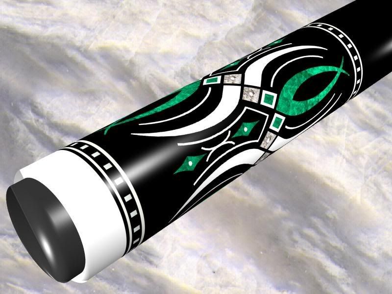
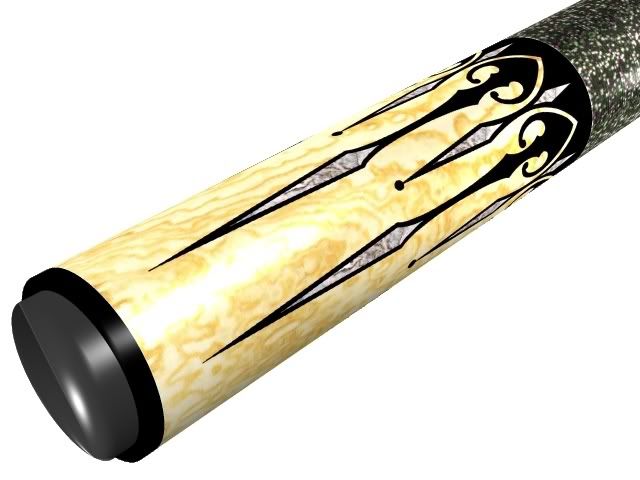
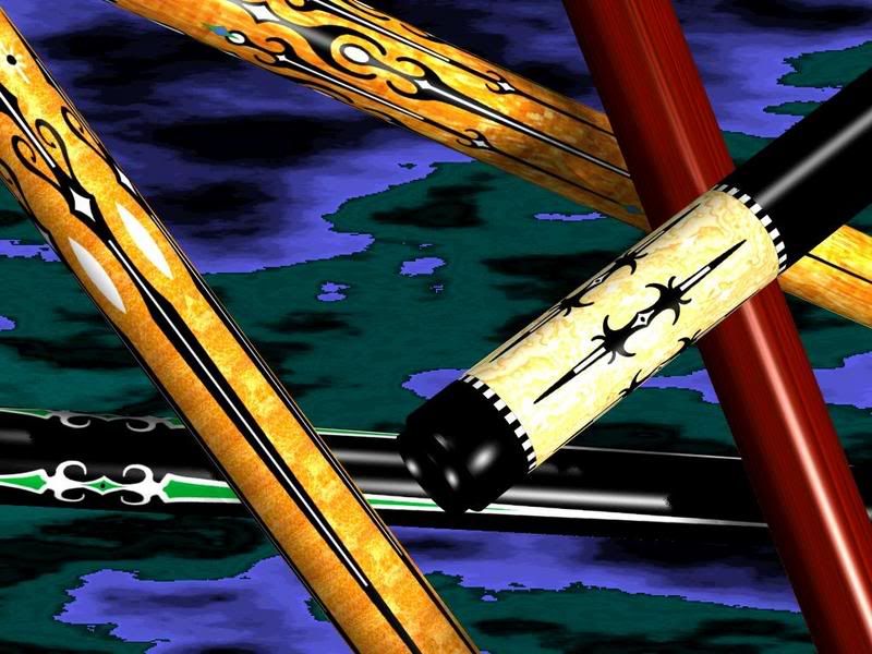
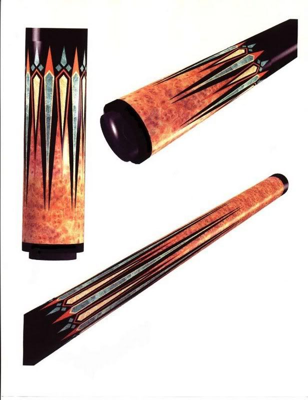
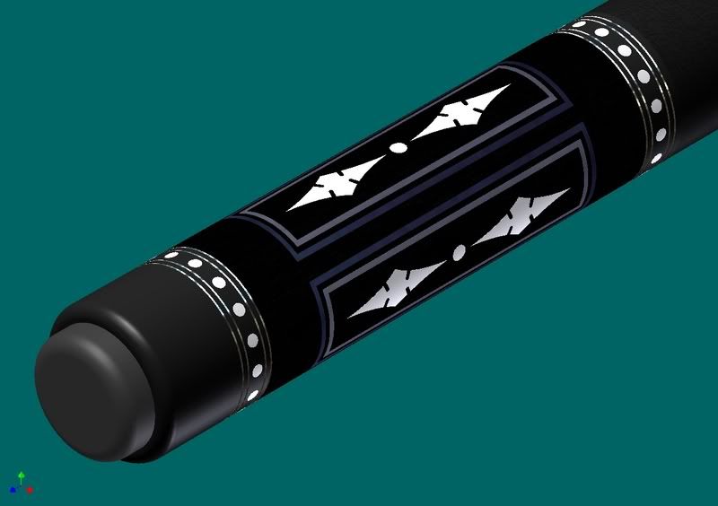
skins said:Photoshop. those are actual photos of butt sleeves cropped and layered over a background of another picture of forearms that has had an monochrome embossing filter added to it. the software i use to initially design cues is CorelDraw. i then import the "flats" into an older simple 3d program oddly enough called Simply 3d. both have a significant learning curves but over some time you can get pretty decent results like these pretty quickly once your 3d templates are created. it gives you a decent representation of what the cue will look like finished. these examples are pretty old. they're before i had ungraded my textures of woods wraps and such..................
I think I saw some of that design from Colorado Cues before he went AWOL.merylane said:have all those been made? some look familiar.
merylane said:have all those been made? some look familiar.
JoeyInCali said:I think I saw some of that design from Colorado Cues before he went AWOL.
Joey~Having Deja Vu~
cutter said:Great looking designs. I messed around with corel draw years ago. Can you now take the corel files and convert them into something a cad program can use. That was the big problem back then, rastor vs vector.
Thanks
Cue Crazy said:Very Kool Looking designs.
Greg
")
cutter said:Can you now take the corel files and convert them into something a cad program can use. That was the big problem back then, rastor vs vector.
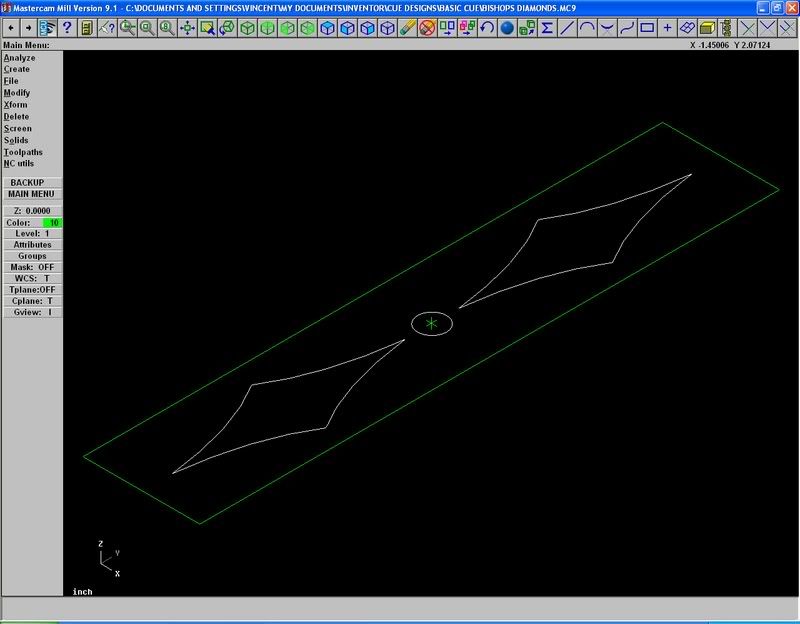
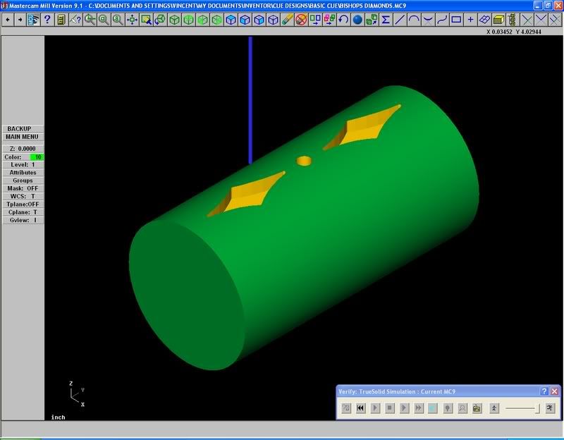
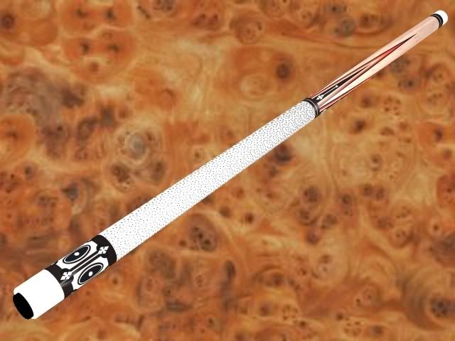
Canadian cue said:If you use Inventor you can export your sketches you used in designing a cue and import them into cam. From there you can create a program for either cutting pockets directly into the cue. Or if you are using a pantograph you can use the tool path to build a pattern. Here is an example of a simple design.
skins said:Photoshop. those are actual photos of butt sleeves cropped and layered over a background of another picture of forearms that has had an monochrome embossing filter added to it. the software i use to initially design cues is CorelDraw. i then import the "flats" into an older simple 3d program oddly enough called Simply 3d. both have a significant learning curves but over some time you can get pretty decent results like these pretty quickly once your 3d templates are created. it gives you a decent representation of what the cue will look like finished. these examples are pretty old. they're before i had ungraded my textures of woods wraps and such..................
Very Nice....Look into it, and maybe have some questions for you
Canadian cue said:Hi skins, In the example I provided I drew no radius on the diamonds and in the mastercam I used a 1/32" cutter. If I were to build the cue exactly as I pictured I would have to knife my corners in. If I were to radius the corners on the inlays I would do my original drawings with the same radius that I anticipate the cutter to have. So I do not believe your point to be a real issue, at least it hasn't been for me.