Limit switches on a deluxe

Cue Crazy

AzB Silver Member
Silver Member
Wondering if anyone here has rigged up a limit switch to their powerfeed on a hightower lathe. I know it's not astro physics or anything here, just trying to get a few ideas before I make My mounts in case i'm missing anything obvious.:D

My switches are both NO or NC, so I believe I can go eitherway, but I really don't want to build a ramp, and was just going to use it as normally closed, and make a mount with a small wing nut, so I can attatch it easy to the carraige when I mount the powerfeed, and unattatch easily when it's not in use. Another reason I'm considering going this way is so I don't have wire running everywhere. Just a small strip from the powerfeed to the switch. I was thinking of using a small single wide riser block from a tailstock to make my stop from for the switch, that way I can easily make ajusments.

Anyway, it's not a hard project, but I would Be interested in hearing what Kind of setup others have made.:)

Thanks Guys, Greg
 
Limit Switch On Hightower Lathe

Hi Greg: What I did was use two 3" angle braces and placed them on the table so that the toggle switch on the feed control tripped them. I made a small extension on the toggles with plastic tubing and clamped the braces to the bench. Works like a charm. If I get time tomorrow I will post some pics.

I am looking for pics on mounting a dial indicator on the deluxe cross feed???

Bob Flynn
Denali Pool Cues
www.denalicues.com
 
Is this what your looking for?
dial1.jpg

dial2.jpg
 
Hey Bob, thanks for the imput. Sounds like something very similar to what I was using before, only I had a piece of angle spring clamped to the table at an angle so It hit the toggle as It finished a pass, and You are correct it does work, I'm just cleaning things up alittle bit I suppose with the limit switch. The parts are cheap enough, so I figured why not.:)

The only picture of an indicator setup I have is this one that I mount to the headstock to zero stuff in with, but that's about all It's good for. I milled it from a solid block of aluminum, and can remove with just one bolt, although I am gonna make a wingnut for it, just that It's still quick to change out like it is so I didn't even bother yet up to this point. It would be much easier to mount one in the tool post though. Chris has one in his new video, and it is much like one I have had in mind for cutting rings off. I don't want to give it up here for Him, so I won't, but I was going to make something pretty much the same for mine. I believe someone mentioned he sells them at a reasonble price though. Seems like he may have one to zero stuff in with too, so You may want to talk to him. I know some things I have gotton from him, I couldn't make much cheaper Myself, and not to mention without alot more hassle involved getting what I need and setting tooling up to do It. Just depends on what it is.:)
 

Attachments

  • indicatorbracketzero3.JPG
    indicatorbracketzero3.JPG
    98.1 KB · Views: 464
Dial Indicator For Cuesmith

RDCustomCues said:
Is this what your looking for?
dial1.jpg

dial2.jpg

Hi RD: Thanks for the reply. Actually I was looking for some ideas for accurate measurement of how much material I was removing using the cross slide. I was able to come up with something for my Unique lathe and my Grizzley has a DRO, but I am kind of stumped with the deluxe cuesmith because of the storage cabinet. Maybe I can sweep the cabinet and see how parallel it is to the lathe bed. I have a set-up for zeroing the out-of-roundness and for sweeping stock mounted between centers.

Best regards,

Bob Flynn
www.denalicues.com
 
Lol

Thanks for clearing that up, I was just looking at Your site through the other thread, and when I saw the equipment you have, I was starting to think you were pulling My leg or something needing an indicator design. Now I see, and understand why I think.;)

I usually just use My calibers and bump everything in on My tenon diameter, so I have no setup for that. What If you mounted a stop to the back of the carraige somehow, and mounted the indicator to the crosslide? Would that give ya what You need? I've been soldering some wires up, the fumes may be getting to My head right this second, so If I'm off base, and missing the point My appologies.:D
 
Well, I wired a switch up last night, everything worked well, the toggle still moves It in both directions:p 
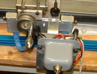
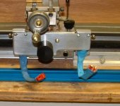
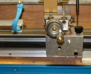
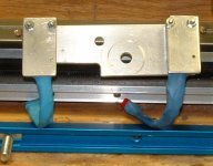
, and the carraige stops on a dime. I wired a short harness up last night, soldered the switch and a plug into it & heat shrinked everything. I also made a jumper plug, so I can use it with or without the switch, I think I'm going to wire another switch into it for the other direction, so I don't have to switch sides with the one when I want to run both ways. I just have to think up a design for a quick release mount for them now. Oh btw the plugs I used are used with hobby rc car batteries, so there's not much chance of the the plugs ever melting. There's no way this feed will put the kind of draw and heat on a plug that those rc cars put on them, and these plugs hold up to that, when many others fail. They are an after market replacement for the ones that fail, and are tough as nails.:)
 
RDCustomCues said:
Are they deans plugs? Any pics of the set up


Yep, They sure are.:) I got lucky, My brother messes around with the RC cars, and so He had a small bag of them. Didn't even have to get in the truck & go hit the radio shack up:p That sure worked out nice.:D Amazing how close the terminals are to the plastic and how the iron doesn't melt them when soldering the wires up against them so close. It's sort of overkill I guess, but they were on hand and free.

I just made a plate to sit up flat against the carraige front to mount the switches to. I had to mill out a slot on one side to clear the pinion and coupling, but looks like it may work out nice. One on each side.

I had a piece of that blue t-slot from rockler, and It looks pretty close to the thickness of the oak base of the deluxe, so I was thinking I could mount the t-slot to edge of the oak, and mill out 2 stops that sit flat on the top, slide up and down anywhere on the lenth of the bed, and lock down from the edge. Everything could be removed easily for when I'm not using the setup. That's starting to sound better to Me then My original idea of using a riser to make My stop from. These would be more out of the way and independent from the bedway It'self.

No pics yet, but I'll post some when I get everything setup. Greg
 
OK, I said I would show this, so here is what I have so far,

This one turned into alittle more of a project then I originally intended, but I have the switches wired and mounted to the carraige. That part is done, but I still need to clean up the tool marks ,scratches and polish the mounts again. I also haven't turned the profile on the delrin knob that holds the plate on yet. Please excuse My fabrication skills guys. They are not top knotch I know, but then I wasn't ever a machinist by trade before either, so function is My main concern as usual, and It seems to pass that test so far. The switches I don't know how long they will hold up, but they are cheap in price, and seem to work really well up to this point, and from what I know of them, if they do go bad, they just won't provide any current to the stepper. There should be minimum risk of them not shutting off though and crashing should they go bad. Usually with this NO setup, they just won't start back up if they go bad, but if they do start up they will usually shut back down.

I did Have to make two modifications to the carraige. The only way I could figure avoiding that was to clip the plate from the bottom lip somehow, but that just didn't seem feasable enough to hassle with to Me, because the castings aren't perfectly shaped on the taig carraiges, except for where they need to be, and have been machined, so I elected to go this way. What I did was turn a dowel, then pressed it into a hole I drilled into the carraige, this was to act as a alignment pin, that way I only had to drill and tap one hole for the delrin knob that holds the plate on. It works as a quick change setup just like I attended It to do, so that part worked out nice.

All I have to do is put the plate up there using the alignment pin, slide the knob threads in and tighten. The switches are plugged for easy fast connections. The whole unit comes off as fast as it goes on, and then allows Me to use the powerfeed without the switches or to use the hand wheel for manual operations.

I still need to make the stops, and I think I will make them so a plunger is mounted to them and is spring loaded, so all I have to do is pull them to restore power to the powerfeed to travel back in the other direction. In doing them that way, I don't have to move My stops away from the switches, risking the loss of My original stop positioning, or have to switch plugs to restore power to the stepper. I just pull back on the spring loaded plunger, flip the switch going the other other direction, release the plunger and It should pop right back to the original positoning. It seems simple enough, so We'll see. I have some cue work built back up that I need to do, but when I get some more spare time I will try to make those. I am still going through all My junk and scrap boxes trying to find the best, parts to machine them from. I'll post those when I'm done though.:) Greg
 

Attachments

  • limitswitch1.JPG
    limitswitch1.JPG
    84.8 KB · Views: 241
  • limitswitch2.JPG
    limitswitch2.JPG
    89.6 KB · Views: 238
  • limitswitch3.JPG
    limitswitch3.JPG
    86.8 KB · Views: 230
  • limitswitch4.JPG
    limitswitch4.JPG
    63.1 KB · Views: 221
Back
Top