Hey Guys,
I've been fiddling around with this problem for almost 3 days now, so I thought I'd try to explain it here.
I want to change my home switch on my CNC taper attachment from a mechanical limit switch to an optical switch. There's just too much variance in the mechanical switch to get a reproducible result.
The problem I'm running into is getting Mach3 to recognize that the optical switch has been triggered. My CNC controller is a Gecko G540. I have the signal lead (orange) from the optical switch attached to pin 2 on the Gecko.
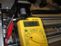
In the first couple of pictures, you can see that when I trigger the optical switch, I am getting the signal output that I expect:
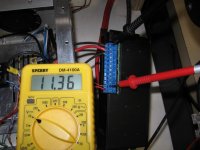
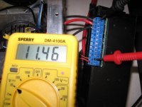
But at the Gecko Controller, I am not seeing 0V and ~5V, instead I am getting a variance between 11.36V and 11.46V, not enough for the Gecko to recognize.
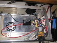
And finally, here is my 5V source for the optical switch. The Blue/BlueWhite pair is the +5V source and the Brown/BrownWhite pair is "ground" or negative. The probem seems to be that when I measure between +5V and gound at the optical switch I see the desired result. But when I measure at the Gecko controller, it only sees a very small voltage change - not enough for it to recognize. There is no ground pin on the 48V-5V power module.
How can I overcome this?
Thanks very much for any guidance.
Gary
I've been fiddling around with this problem for almost 3 days now, so I thought I'd try to explain it here.
I want to change my home switch on my CNC taper attachment from a mechanical limit switch to an optical switch. There's just too much variance in the mechanical switch to get a reproducible result.
The problem I'm running into is getting Mach3 to recognize that the optical switch has been triggered. My CNC controller is a Gecko G540. I have the signal lead (orange) from the optical switch attached to pin 2 on the Gecko.
In the first couple of pictures, you can see that when I trigger the optical switch, I am getting the signal output that I expect:
But at the Gecko Controller, I am not seeing 0V and ~5V, instead I am getting a variance between 11.36V and 11.46V, not enough for the Gecko to recognize.
And finally, here is my 5V source for the optical switch. The Blue/BlueWhite pair is the +5V source and the Brown/BrownWhite pair is "ground" or negative. The probem seems to be that when I measure between +5V and gound at the optical switch I see the desired result. But when I measure at the Gecko controller, it only sees a very small voltage change - not enough for it to recognize. There is no ground pin on the 48V-5V power module.
How can I overcome this?
Thanks very much for any guidance.
Gary
Attachments

Last edited: