cutting inlay pockets with tiny cutters

Yes, I've seen that & I respectfully disagree with that. It goes against all conventional wisdom regarding sound machining practices. In fact, most high speed CNC machinists NEVER conventional mill a profile.

Not being an experienced high speed machinist I cant say anything about cutting metal on a CNC machine.
But as an experienced cue maker who does CNC inlays in wood pool cues I can say this ....

I CLIMB CUT (counterclockwise) the pocket with a spiral pattern then take one clean up cut following the last tool line but using the conventional cut (clockwise).
This almost always cuts off a strip of wood that measures about .003" in thickness.
Had I stopped with the climb cut the pocket would have been .003" smaller than wanted in some places.
This dont sound like much but it makes a difference in the way the inlay parts fit the pocket.
(I do the same when cutting inlay parts)

The Desk NC program I use to drive the CNC has adjustable parameters for deceleration of feed speed when changing directions or cutting arcs.
 
Last edited:
Enlightening tests

Since I never actually tried conventional milling a pocket in wood, I figured I should at least give it a shot. So I did.

Just did the simple test I proposed earlier with the addition of making 2 inlays using both milling methods. Let's just say this old dog is eating some crow with spilled milk, to mix my metaphors. Turns out that working in wood is not the same as working in metal.

I was surprised to see that both the pocket (in maple) & the inlay (snakewood) came out very close with no corner issues. As expected, the pocket & inlay that were climb milled had a slightly tighter fit but the conventionally milled sample went together just fine. I would have expected a more drastic difference.

That said, I will still continue to do things the way I always did since it works well for me. But I will not be so quick to dismiss another method without at least giving it the benefit of a trial run.

Quick pic attached. No glue was used - a tribute to the accuracy of either method. Also, note that I used ZERO offset for all parts & all parts were programmed to the same size. I just rough sanded the inlays flush so it isn't the neatest install.
 

Attachments

  • climbtest.jpg
    climbtest.jpg
    97.8 KB · Views: 325
In toolmaking , we mainly use relief/stepped milling cutters.
When ever possible climb mill.
Depth of cut varies to cutter length to diameter ratio and material being cut.
eg 3mm emill 30 mm long in mild steel can run 10k 1mm depth cut and 1500 mm/min for a full width cut.In P20 die steel, aprox 34 Rc cut depth is reduced to 0.4 mm but feedrate is still 1500 mm/min.These are for 4 flute carbide cutters that only cut for max 1 diameter deep on the side of the endmill. From 1 dia up,the cutters are solid with no flute and relieved by 0.1 to 0.2 mm on diameter.
When finishing a profile or pocket,we always climbmill and 1st choice is to continually ramp down with the cut.I ramp down at a rate of no more that 45% dia of cutter.
A 3 mm endmill ramp rate is 1.3 mm down per profile.
10 d is the safe max distance that we mill pockets. Any deeper ratio and we look at other methods.The smallest cutters we use are 0.8mm to 8 mm deep.
Small cutters need to be running true,with adequate chip removeal in a ridgid stable setup.Rapid changes in cutter load or feed cause fatigue in the cutter,causing premature failure.Through spindle cooling/air mist/coolant is best.Most machines these days offer this option.
 
Bill the Cat. No I don't do the final claen up cut completely at full depth. I break way too many tools that way. I use the diameter/depth method for all cuts, including the final clean up pass. Has worked well for me. True, it takes longer, but with CNC, start it up and go do something else and let er' eat.
 
I can see your point on something like floating points but I'm only talking about small, delicate inlays...where a trip around the whole perimeter isn't a big deal.

I have, on occasion, done exactly what you describe - isolate the tight spots & create separate programs - but the remachining function (which I just found) automatically takes care of that.

You said you cut in a clockwise direction but you didn't say if that was for an inlay or a pocket. I always climb mill pockets - in a counter clockwise direction - to avoid the cutter's tendency to "dig in" in the corners when conventional milling. It is the preferred method unless you have backlash problems. With finish cuts this shallow it might not make a difference...I just do it because I've done it that way all my life. I still suspect it would make a difference in tight corners though, simply due to the increased cutter load as shown above.

MC doesn't have an "arc slowdown" function but it has a highspeed function for exactly the same purpose. I suppose should look into that, too. I just learned about the "remachining" function yesterday. Maybe today brings more new tools!

Thanks!

Ok Bob, I offset pocket out ccw in steps and profile at full depth with smaller cutter in cw direction. I learned this as Bill stated from Precise Bit's web site. I was at Jenson cues last year and we had issues cutting in inlays. They wouldn't fit. Now these inlays where flurs that needed a .020" cutter and had outside and inside circular cuts. They would not fit very well. Some areas where too big, and others too small. When we followed this method from Price bits every thing fit perfect. So anyways, can I assume that you are using Mach3? If so have you concidered using G61 for your smaller bits? G61 turns on exact stop instead of the G64 for Constant velocity. In constant velocity mode your corners will be rounded a bit. I have heard of other cue makers turning down their acceleration in motor tunning are to fix the tool slamming issue. I don't care for this as the axis is not very stiff when moving to positions. I actually broke bits just jogging around as the axis still moved even after I released the jog button on my pendant.

Jim.
 
Dzcues

take another pic of those two lays you put up,but do them horizontal.and dont do them so close,back off them a little.i see something,maybee it is an
illusion.but lets check.

bill
 
Since I never actually tried conventional milling a pocket in wood, I figured I should at least give it a shot. So I did.

Dang Snakewood ... cracked already ... :eek:

Hey ... that design looks good.
4 times around the butt ... sprinkle in some dots ... masterpiece ... :happydance:
 
Last edited:
Ok Bob, I offset pocket out ccw in steps and profile at full depth with smaller cutter in cw direction. I learned this as Bill stated from Precise Bit's web site. I was at Jenson cues last year and we had issues cutting in inlays. They wouldn't fit. Now these inlays where flurs that needed a .020" cutter and had outside and inside circular cuts. They would not fit very well. Some areas where too big, and others too small. When we followed this method from Price bits every thing fit perfect. So anyways, can I assume that you are using Mach3? If so have you concidered using G61 for your smaller bits? G61 turns on exact stop instead of the G64 for Constant velocity. In constant velocity mode your corners will be rounded a bit. I have heard of other cue makers turning down their acceleration in motor tunning are to fix the tool slamming issue. I don't care for this as the axis is not very stiff when moving to positions. I actually broke bits just jogging around as the axis still moved even after I released the jog button on my pendant.

Jim.

Jim,

Thanks for your clarification.

I'm not having "tool slamming" issues. It's just common knowledge that when machining metal, climb milling is preferrable for getting clean cut corners. (see conetip's post #23) He knows where I'm coming from. Climb milling is standard practice in metalworking. And that habit carried over into my cuemaking.

However, my test has shown that this really isn't an issue in wood. I suspect your inlay fit problems were solved when using conventional milling because your cutter pulled into both the inlay & the pocket, giving you more clearance.

PS I'm using MasterCam...not Mach3.
 
Dzcues

take another pic of those two lays you put up,but do them horizontal.and dont do them so close,back off them a little.i see something,maybee it is an
illusion.but lets check.

bill

Not sure what you want. How's this?
 

Attachments

  • cutter-engagement2.jpg
    cutter-engagement2.jpg
    91.8 KB · Views: 293
dzcues
lol, thats a little to small.i wanted to compare corners.

i use to do some street racing in erie,pa back in the late 60's.it was a hot spot.we pulled from toledo.their were guys that came from all the surrounding states.it was a big time.

bill
 
dzcues
lol, thats a little to small.i wanted to compare corners.

i use to do some street racing in erie,pa back in the late 60's.it was a hot spot.we pulled from toledo.their were guys that came from all the surrounding states.it was a big time.

bill

I did some of that, too, but it wasn't until the early 70's. I had my engine work done at Myle's Engineering in Cleveland (halfway between here & Toledo). I'm helping my son get his project on the road now. My '65 Chevelle is shown there, along with my current ride, a supercharged Mustang.

Do you remember any names from Erie? Gentile? Sack? Agnello? Vergotz?

Regarding the corners...they look almost identical after I sanded it down better. In this admittedly simple test, I found no difference in the final results. Sharper corners - like in a long thin diamond - might make a difference but I spent enough time on this today. Gotta get back to making cues.
 
Bob,

I like the test, but it only shows outside corners.

I am always worried about tool deflection and I think it will show the best, or worst LOL, when you go from an inside corner to an outside corner.

How about trying a Star inlay. I think that would show plenty of both. As a matter of fact, I think I will try one. I will have to draw it up first and I have a full day ahead of me, but I will try one and post the results. I don't have a machine like yours, but I will see what my little machine can do.
 
Bob, How about trying a Star inlay.

I ran a quickie for you.

Small pic shows the concept but THIS LINK will take you to a larger picture.

Please believe me that both inlays look very nice when viewed actual size in real life. It's surprising how something that looks this good in person can look so bad when enlarged.

As explained, left side was conventional milled, both inlay & pocket, while right side was climb milled. The conventional milled inlay fit very easily while the climb milled part was snug, yet pushed in with light finger pressure. Inlays were marked before installation so orientation of the star was kept consistent with pocket orientation.

The conventional milled inlay shows obvious clearance on just about every point and the climb milled inlay, while not perfect, is noticeably better.

There was no glue used here but a light coat of Krylon clear was applied for contrast.
 

Attachments

  • star-test-small.jpg
    star-test-small.jpg
    98.7 KB · Views: 364
Bob,

Wow! they do look good, but not as much so up really close.

So, did you cut these like you said earlier, profile first and then rough?

Also, what are you using for a spindle? I know you've gone through some changes, but I'm not sure I know where you ended up.

I didn't get a chance to fire up my spindle today, so I didn't cut anything. I will try tomorrow. The only machine I have right now that I could use for inlays is a Taig milling machine, and I know it has some backlash in it. I am building a couple of new machines right now and should be much better equipped for this kind of work soon. I also have a really high end spindle, but I need a cooling system for it so I have some work to do yet to get it up and running.

I should have done them the way I alway do it - profile first, then pocket - but I was curious how this method would work.

For both of them, I pocketed without a finish cut, leaving .002". Then I did a ramped profile cut at .000 offset to clean up the big areas safely, then a final pass at full depth, also at .000 offset. Cutter was .020" w/.125 DOC. Inlays were .125 thick but pockets were only .100" deep. When I hogged off the excess inlay material, I didn't realize I'd chipped one of the points (on left star).

Normally, I'd use my high speed spindle (see my 1st post in this thread) but I just used my Bosch with the PreciseBit collets so I could squeeze it in between real work with a minimum of downtime. I did check the runout before starting and the cutter had .0012 TIR.

FWIW, inlay design & program took about 15 minutes while I figured out what I wanted to do. I let that program run while I designed & programmed the pockets. All told, test took about 30 - 40 minutes. Feeds were 8 ipm for all roughing cuts & 6 ipm for finish pass. Overlap on pocketing passes was 60%. Step & ramp cuts were .015" deep. I was conservative because of extra long cutter. I ordered them by mistake & usually use .090" DOC cutters for better durability.

I'm curious to hear/see how your Taig does. The photos really do show the flaws. Keep in mind that even the small picture posted above shows the inlay about 4X real size.
 
Bob, what do you mean?

Bob, what do you mean zero offset? Do you mean that you didn't add or subtract from your tool diameter to figure out toolpath? In Bobcad 23, I set the diameter of my tool and the cam computes the tool path based on my radious of the cutter. The reason that I ask is, if you have to put in a diameter of your cutter, how do you know that you have no offset? This is splitting hairs of course. I am also wondering what software drives your cnc machine? I would say at this point that it is not Mach3 based on some of your comments.

thanks, Jim.

Jim,

When you chain your geometry in the direction you want to go, tell it if you want to cut on the right or left side of the profile & give the diameter of your cutter, the program generated will automatically offset your cutter by its radius. This is considered .000 offset. In a perfect world, you will get exactly the size you want. If your inlay/pocket is not to size, you can simply dial in a plus or minus .001" or .002" (or any number) offset which is added to or subtracted from the tool radius.

This is essentially the same as what you described, except instead of cheating by changing the tool diameter, I tell it exactly what amount of adjustment I want.

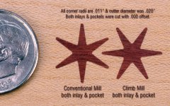
My point in mentioning that I used .000 offset was to show that I did not manipulate the cutter size to achieve a desired result. When climb milling, both parts came out very close to design size, allowing a very snug fit. When conventional milling, the cutter "pulled" into the inlay (making it smaller) and also pulled into the pocket, making it larger. Hence the increased clearance that allowed for the easier assembly.

This feature allows you to use the same geometry for both inlay & pocket. You simply chain in the opposite direction for the other toolpath.

My Techno comes with a controller & proprietary software. Click the link for more info.

The attached pic shows the parameters I used on one of the pockets. Look at the right column. The compensation is automatically calculated in the computer. Cutter comp is to the left of the chain direction. And near the bottom, it says "XY stock to leave" - this is where you can dial in a positive number (.002 for the rough cut), 0.0 for no offset or a minus number if I wanted the pocket to be slightly larger. The beauty of this is that if a pocket is slightly tight, I can call up this screen, change the offset to -.001", regenerate the program & try again. It only takes a few seconds.
 

Attachments

  • offset.gif
    offset.gif
    35.1 KB · Views: 326
FWIW, here's a look at the other screen, showing my finish feed rate of 6 ipm, plunge/retract rates & the tool diameter as .020". These screens are for the finish pass on the profile of one of the star pockets. The other is identical except the chain goes the other direction & cutter comp is to the right.
 

Attachments

  • offset2.gif
    offset2.gif
    28.7 KB · Views: 319
Thanks

Thanks Bob, it is always interesting to actually see what others are doing.

Jim.
 
Thanks Bob for helping make this one of the most useful and informative topics I have seen here in a long time.
Good information backed up by good research.

Know your time is valuable so again, thank you for posting all this.
 
Back
Top