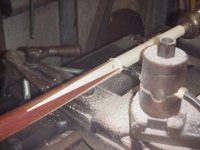
I finally got out to my shop with a camera and took some pics of the taper bar I made. The first pic (the out of focus one) is of the bar that attaches to the cross slide. I have been playing around with brushes and covers to keep dust off the bearing. The others show the taper bar Assembly which is overall 48" long. The actual taper bar is 36" long with 32" of bearing track. The cool thing about the setup is I can go from regular turning to cutting tapers in about 3 to 4 minutes. Also I have mounting holes already in the main bar for another taper bar that I am having made that has 2 tracks: 1 for straight taper 1.25" butt to .850" joint and another track with a compound taper for the shafts. You can see the additional bearing mounting holes on the cross slide bar. The bad thing so far is the dust getting in the track. I am currently working on this with better vacuum setup and a clear acrylic shield. One of the pics also shows the rear chuck which is a must, huge time saver. If you are buying a new lathe I would suggest no smaller than 13" x 40". Better to have a little extra than be a little to small.
This is an Enco 13" x 40" lathe I have had since 1987. I believe the casting is still used on a Grizzly lathe as well as some others.
Oh I just noticed on more thing: The quick change to post with router mount is a must for us one lathe guys.
Good luck,
Troy Mckune


")

") The tailstock can easily bow the shaft between centers if too much is used.
The tailstock can easily bow the shaft between centers if too much is used.