Tips or Tricks for inlay pockets?
- Thread starter moccabee
- Start date
Are there any tips or tricks that you use to ensure your the pocket for your inlay will be centered? I will be inlaying my first set of diamonds in to a butt sleeve and want to make sure they are centered within my veneered window.
Thanks
Get a head band magnifier. Put in a small tool. Bring the tool down with in a few thou. Rotate A axis until the tool lines up with one side..... I look at the side of the tool and the inner veneer. Get your head right in there and look straight down the veneer line and not at an angle.
When it's lined up, zero A axis,
Rotate A axis until the veneer on the other side of the box lines up with the tool.
Look at the A axis DRO.
Rotate A axis back 1/2 the number of degrees.
Zero A axis,
Kim
RBC
Deceased
Get a head band magnifier. Put in a small tool. Bring the tool down with in a few thou. Rotate A axis until the tool lines up with one side..... I look at the side of the tool and the inner veneer. Get your head right in there and look straight down the veneer line and not at an angle.
When it's lined up, zero A axis,
Rotate A axis until the veneer on the other side of the box lines up with the tool.
Look at the A axis DRO.
Rotate A axis back 1/2 the number of degrees.
Zero A axis,
Kim
Make sure you're Y axis is centered first!
Also, a little trick that many don't know about.
Instead of remembering what the A axis number is, and jogging back to half of that, you can just click in the DRO for the A axis and type " /2 " and hit enter. It will automatically divide whatever was in the DRO by 2. Then you can just zero the A and you'll be set.
I can't take credit for that little tidbit of information personally. Jim Babcock, MC2 here on AZ, was the first person to tell me about it.
Royce
One thing you can do is scribe a line down the cue. I do it in the lathe with a spring loaded pencil I mount in the tool post. I rotate the cue until I find the center line of the geometry. I usually reference off of a point in the forearm. Then I scribe a line the length of the cue. When I am doing inlay I start by finding center on the Y as Royce mentioned and then I rotate the cue in my dividing head until my scribe line and my cutter are in line. Another method of finding center on your Y is to put a center in your dividing head or indexing head and a center in your spindle. Bring the two points together and you are now in the middle of the Y axis.
We needed to put some rubies into the middle of fancy Ivory points in several places in each point and we can't cut the pockets for those ahead of time like you can for normal inlays. So what we did was program a small drilled hole exactly where we wanted to come back and cut the pocket. My son would then drop the bit into the little drilled hole and that would put him right where he needed to be to cut the pockets for the rubies. But then again with normal inlays going into your pockets you could just program that pocket ahead of time.
But for putting inlays inside v-groove points the method Kim gave is pretty much what we do.
But for putting inlays inside v-groove points the method Kim gave is pretty much what we do.
Get a head band magnifier. Put in a small tool. Bring the tool down with in a few thou. Rotate A axis until the tool lines up with one side..... I look at the side of the tool and the inner veneer. Get your head right in there and look straight down the veneer line and not at an angle.
When it's lined up, zero A axis,
Rotate A axis until the veneer on the other side of the box lines up with the tool.
Look at the A axis DRO.
Rotate A axis back 1/2 the number of degrees.
Zero A axis,
Kim
Far easier is to put in a 30-degree drag-style engraving tool - this is simply an 1/8" diameter carbide rod with a point ground to 30-degrees (no cutting flutes). Now you don't have to worry about a parallax error caused by viewing one edge at a slightly different angle from the opposite edge.
Because I have automatic tool changing on my spindles it's especially easy for me to do this, but even if you have to pull out the wrenches it's worth the peace of mind that will come from knowing the angle of your viewpoint is basically irrelevant to the resultant accuracy.
TW
.
harris cue comp
Banned
camera
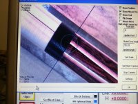
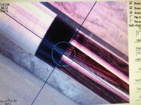
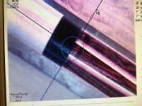
I have a camera attached to my spindle. I line the crosshairs up with each side of the point and go to center. There is a an offset number that I type in the dro and the endmill goes directly to where the crosshairs were.
Robert Harris
I have a camera attached to my spindle. I line the crosshairs up with each side of the point and go to center. There is a an offset number that I type in the dro and the endmill goes directly to where the crosshairs were.
Robert Harris
Attachments
RBC
Deceased
I have a camera attached to my spindle. I line the crosshairs up with each side of the point and go to center. There is a an offset number that I type in the dro and the endmill goes directly to where the crosshairs were.
Robert Harris
You should load those numbers into a macro as incremental moves and have it called by a button on screen.
Royce
harris cue comp
Banned
short cut
Royce: it doesn't take that much time, even though I appreciate the thought. I couldn't save more than seconds by hitting a single button. But it is cool how I do it. You don't have to worry about looking into the mill as the image is directly above the cue.
Thanks
Robert Harris
Royce: it doesn't take that much time, even though I appreciate the thought. I couldn't save more than seconds by hitting a single button. But it is cool how I do it. You don't have to worry about looking into the mill as the image is directly above the cue.
Thanks
Robert Harris
RBC
Deceased
Royce: it doesn't take that much time, even though I appreciate the thought. I couldn't save more than seconds by hitting a single button. But it is cool how I do it. You don't have to worry about looking into the mill as the image is directly above the cue.
Thanks
Robert Harris
Robert,
Yea, I know it's easy. I've used cameras for a while now.
One thing I do with the buttons is use them to verify my camera alignment. Sometimes they can get bumped out of position.
I have one button that is programmed to go from the tool to the camera. So, I make a small hole either in some scrap or on my table where it won't matter. (I have sacrificial tables on most of my machines) Then I just hit the button and the camera moves over the hole. If it's been bumped, I'll see it and just adjust the camera to center over the hole.
Also, after I've cut something small and I want to get a good look at it, I can hit one button and then see it on the video window all nice and up close. Then, just hit another button and I'm back to where I started from.
Camera's are pretty cool, but I still find that I don't use them as much as you might think. With fixtures and work offsets, most of my programs already know where they are, but I do like my toys!
Royce
harris cue comp
Banned
cameras
Royce: as a one man shop with only 5 cnc machines, I only use this on the 30 by 60 mill that I use to cut pockets in with. The other 4 mills are set up to do one function. I'm setting up a cnc machining center similar to the one you have doing collars at present. The programming for that is a whole new process.
Take care
Robert Harris
RBC
Deceased
Royce: as a one man shop with only 5 cnc machines, I only use this on the 30 by 60 mill that I use to cut pockets in with. The other 4 mills are set up to do one function. I'm setting up a cnc machining center similar to the one you have doing collars at present. The programming for that is a whole new process.
Take care
Robert Harris
Robert,
What kind of machine did you get, or are you building something?
The only commercial machines I have are the 3 CNC lathes. I have an Omniturn on a Feeler lathe, an Accuslide on a Hardinge HLVH, and an old Hardinge CHNC4 super precision.
All 3 program differently. The CHNC has a Fanuc control and uses a turret. It's probably the toughest to program, but it's the only one I can use really long tools on to drill and tap the back end of the cues. It's also the only one I can fit a cue through as well.
It's an adventure, but it's all pretty fun too.
Royce
RBC
Deceased
What type camera are you using and how is it mounted?
There are several different choices out there. Some guys use Dino-lite cameras, but they cost more than what I've been using.
I purchased one off ebay built specifically for CNC. The guy is out of Europe, and they currently aren't available. However, he is redesigning the camera right now and should be sending one to MC2 for testing. I have the first version of his redesign, and it works very well. As soon as they are back in production, I'll get his contact info out to everyone.
Basically, it's just a USB webcam. You can use one of the CNC microscopes too if you want to play around with it.
A few things about mounting that are important.
You want to put it on and leave it if you can.
It should be out of the way so it doesn't get banged around.
I like to mount mine as vertical as possible.
A good camera, like the ones I buy, have adjustments in them so you can get them lined up pretty straight up and down.
In use, I pick a standard height above the work, usually 1" and focus the camera there. I then use my work offsets and/or the macro's programmed into my buttons to always get it to that exact height over whatever it is I'm looking at. You're position can change if you have to adjust the focus, so I just use a consistent height.
Royce
camera mount
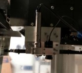
Here's the set up on my Haas. Really saves my back leaning in to find points on the cue. Camera is Dino lite microscope camera. It's way over kill, but my old eyes need all the help I can get. I would recommend really researching the camera before buying. The biggest problem I have found on other camera's is that the
CCD chip isn't lined up with the camera housing. Causes lots of alignment problems.
I run mine thru a separate laptop( not using Mach 3) so I can get whole screen view.
The Dyno lite software works really well and gives you options like designing your own cross hairs.
Attachments
I have a camera attached to my spindle. I line the crosshairs up with each side of the point and go to center. There is a an offset number that I type in the dro and the endmill goes directly to where the crosshairs were.
Robert Harris
Robert I am curious, why do you have your camera orientated like that? What is the advantage?
Thanks, Jim