Turning tips

My biggest thing is to keep everything clean and lubricated...... Especially taig based beds...... A little gunk can jam everything up

On that note if you are finishing cues on the same bed you can cover it with plastic wrap or aluminum foil to protect it from spray or drips

Any HVAC installer can fabricate a steel cover from scraps.
 
I took some phone pictures of making a router mount block, the turning stages.
Pic 1 , Mounting the block in the 4 jaw chuck.
In my case I just put a spot drilled hole to use a dti to get the center position. In my case the hole center position is not critical at this stage as the block is oversize on all finished outer dimensions.You will notice that on the jaw shown with the 2 packers, that it has another jaw on top, that is also inverted.This is used to help counter balance the offset work piece.The packers were used to give clearance for the drilled through hole. The boring bar will stop short of the end of the part.

Edit, Warning, Do not run lathe at High speed when turning with an out of balanced or offset work pieces.
Check that there is clearance with the slides etc and that nothing can get in the way, including the chuck guard etc.
I ran this part at the 230 rpm setting. It could run at 400 or so, but 1, why take unnecessary risk. 2/ keeps the coolant from going every where.


picture.php
 
Last edited:
Pic 2 ,
I like to drill with the largest possible, leaves less to be bored out.
This shows the drill and the boring bar in the shot.
In practice, the boring bar is not left in the holder, just for the pic to show tools being used.
Depending on the power of the lathe, and the rigidity of the set up and work holding capability, you may need to step drill the work piece.

picture.php
 
Pic 3
1st boring op was actually to face off to an area that is going to be the same or bigger than the finished area.This is so that 1, we have a clean face to start boring from, and 2, gives an indication as to how much material is going to be left for the overall height and how far we need to bore through.The facing was done quite quickly/course. A finish face will be done after the bore has been finished.
Rough out the hole with the boring bar with what ever cuts the power allows or the rigidity of the machine allows. Stalling the lathe is real bad news for cutting tool edges, especially carbide.There is no point in taking too big a cuts and getting the work piece hot. This can cause in extreme cases, the work piece to become loose, when the part cools down, and possibly come loose or even out of the chuck.
Think about the cut sizes that can be taken, and the amount to be the finish cut depth.
The finish path cut depth is determined by a lot of things, like how rigid the turning/boring bar is, the tool radius and the material being cut. As a general rule, you can often go ,1/4 to 1/2 the tip radius as the depth of cut, so I used a 0.4mm (0.016 inches )radius tool, so the depth of finish cuts will be about 0.1mm to 0.2mm or (0.004 to 0.008 inches) or 0.2mm to 0.4mm diameter(0.008 to 0.016 inches). Feed rate will be between 1/4 the tip radius to 1/8, .05mm to 0.1mm, (.002 to .004 inches) per rev feed rate.
So my bore is to finish at 43.92mm to suite my router. So I am going to ruf the bore to about 43.5 mm . Then I dial a finish feed rate pass at 43.72mm. Then measure with what ever you have, caliper, tele gauge, bore gauge mic etc. Then see how much more has to come out. Take that cut. Then check it is the correct size.looks like it was at 43.7, so took a 0.22mm finish cut to get the 43.92mm diameter.
picture.php
 
Last edited:
Pic 4,
After finishing the inner bore, then did the final face turn on the front face and any chamfer or radius on the top edge. I only need to face to get a cleaned up face for about 80mm diameter.
This face will be the datum face for all the milling operations next.
Looks real fast , but is actually only doing 230 or so rpm.

picture.php
 
Pic 5
The finished stage of this part.
Inner bore for router is completed, and the top face is trimmed true to the bored face.
Now I have a reference center hole, and a datum face to square and size the block from in the Mill.
I hope these have been helpful to some out there.

picture.php
 
Here is a video clip of a pivoting threading holder.
It allows the user to reverse the spindle , and it seems that the tool lifts up and does not try and double cut a thread. Interesting anyway.
https://www.youtube.com/watch?v=8JFdNaBD5GM#t=263

Another tip, to try and contain dust etc as long as the rpm's are not too high, applying a very sticky grease like substance like O ring grease will capture the dust or very fine swarf etc.

Neil
 
So I don't have live threading set up yet, and made a guide for a 3/8-10 tap. It uses the steady rest as a centralising guide for the tap to make a concentric thread. It came out running to better than 0.03mm TIR which was better than I was expecting. The delrin bush was made with the outside concentric to the 3/8-10 tap and is a light slide fit in the 30mm steady rest. The bush OD is 29.98mm or 1.1813 inch diameter.

picture.php


picture.php


short youtube clip showing runout.

https://youtu.be/AD0e3MJxO_s
 
This may not be new, but tonight used the phone camera to zoom in and more clearly see the compound slide angle mark. Also used it to see the surface finish of the job being turned.
Neil
 
Thanks for sharing Conetip :smile:

As a machinist I am very impressed with your way of doing things. Creative and functional, I am impressed :rolleyes:
 
Thanks Kim for the kind words. If it helps out someone then it has been worth while.
Neil
 
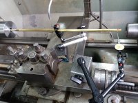
Extended DTI

This is my Extended DTI, it is just an equal length pivot arm using the head of the new Noga DTI holder. I made a bush bearing at the pivot area, and in this case used a piece of 3/8 K&S hard brad tube. In the end is a hardened steel top hat with a 1.5 mm radius. Similar to the 8mm shank one that is supporting the DTI clamp. There is a plastic spacer for the tension of pivot as well. It is with in 0.02mm for roundness and concentricity as compared to just using the DTI directly.As shown in the picture, that was a test to see the accuracy before going down 220mm into the bottom of the hole. This particular piece needs the hole to be as concentric as possible. So I centred the bottom of the hole and the front of the part, then turned the outside to re establish the datum for the continuation of the parts being made. In this case the bottom of the hole was 0.1mm off centre before correction.
Neil
 

Attachments

  • Checking-runout-R.jpg
    Checking-runout-R.jpg
    189.2 KB · Views: 226
Back
Top