I'm putting together something for a homemade lathe and had an idea of wiring something. I could use input from a real electrician who knows if this is ok.
I'll show you what I'm thinking of ...
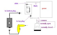
In this drawing, I am attempting to wire a variable speed rheostat to a drill which is used to power a home made pool cue lathe, and use a momentary on / off foot pedal switch for safety.
The plug ends on both the rheostat and the momentary on / off foot pedal switch rather than hard wiring it will allow me to disassemble the setup until the lathe is needed (which isn't very often) so wires are not all over.
The objective is to only submit the momentary foot pedal switch to full power from the circuit breaker box rather than expose it to power AFTER the rheostat so it will not overheat from excess resistance. This is why I want the order of the power flow from the circuit breaker, to the momentary switch and THEN ... to the rheostat and finally to the drill.
The main question is my use of the duplex outlet box. It certainly isn't orthodox and for all I know, there may be a specialized plug end configuration to do what I have in mind. This is why I ask.
Rather than normal wiring of white to one side on top and black to the other, I want to wire the Hot (black) wire to the silver (white terminal) on the top plug. Then allow the metal lug to carry the hot voltage to the gold (black side) of the bottom plug.
The white wire will go directly to the bottom silver screw on the bottom plug.
The momentary switch has three wires ... Common, Normally Open, and Normally Closed. I will not be using the normally closed wire.
I want to wire the Common and the Normally Open wires to a Male Plug which I can plug into the top of the Duplex outlet. This will feed current into the common of the momentary foot pedal switch.
When the foot pedal is depressed the circuit will complete and run through the normally open wire back up to the right top side of the Duplex outlet. The steel lug will carry the power down to the hot side of the bottom Duplex plug allowing the Rheostat to be powered.
Can I do this in this manner?
I'll show you what I'm thinking of ...
In this drawing, I am attempting to wire a variable speed rheostat to a drill which is used to power a home made pool cue lathe, and use a momentary on / off foot pedal switch for safety.
The plug ends on both the rheostat and the momentary on / off foot pedal switch rather than hard wiring it will allow me to disassemble the setup until the lathe is needed (which isn't very often) so wires are not all over.
The objective is to only submit the momentary foot pedal switch to full power from the circuit breaker box rather than expose it to power AFTER the rheostat so it will not overheat from excess resistance. This is why I want the order of the power flow from the circuit breaker, to the momentary switch and THEN ... to the rheostat and finally to the drill.
The main question is my use of the duplex outlet box. It certainly isn't orthodox and for all I know, there may be a specialized plug end configuration to do what I have in mind. This is why I ask.
Rather than normal wiring of white to one side on top and black to the other, I want to wire the Hot (black) wire to the silver (white terminal) on the top plug. Then allow the metal lug to carry the hot voltage to the gold (black side) of the bottom plug.
The white wire will go directly to the bottom silver screw on the bottom plug.
The momentary switch has three wires ... Common, Normally Open, and Normally Closed. I will not be using the normally closed wire.
I want to wire the Common and the Normally Open wires to a Male Plug which I can plug into the top of the Duplex outlet. This will feed current into the common of the momentary foot pedal switch.
When the foot pedal is depressed the circuit will complete and run through the normally open wire back up to the right top side of the Duplex outlet. The steel lug will carry the power down to the hot side of the bottom Duplex plug allowing the Rheostat to be powered.
Can I do this in this manner?
")
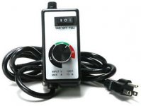
 Also, your rheostat's grounded plug will send a hot to your rheostat housing. Ouch! GL