You are using an out of date browser. It may not display this or other websites correctly.
You should upgrade or use an alternative browser.
You should upgrade or use an alternative browser.
Any electricians here?
- Thread starter 3andstop
- Start date
Here's one that I show customers when selling the benefits of Arc Resistant Switchgear. Always gets their attention. In this video a maintenance worker is racking in a 30 year old medium voltage GE Magnablast air magnetic vertical lift circuit breaker. Only problem is he is racking a closed breaker onto a fault.
https://www.youtube.com/watch?v=J6p2kCiJZXI
https://www.youtube.com/watch?v=J6p2kCiJZXI
The Engineer in me says....please don't do this. If you can't properly diagram this or don't know whether it will work you are not qualified to do this. How would you feel if you hurt yourself or someone else all in the name of saving a few bucks? Find a friend or pay someone.
An improper ground or wiring mistake can ruin a day or someone's life. Arc flashes occur in milliseconds. You would be amazed how much energy is a behind a 15Amp circuit.
https://www.youtube.com/watch?v=Hp1JdVwbN_U
Nick
Here's one that I show customers when selling the benefits of Arc Resistant Switchgear. Always gets their attention. In this video a maintenance worker is racking in a 30 year old medium voltage GE Magnablast air magnetic vertical lift circuit breaker. Only problem is he is racking a closed breaker onto a fault.
https://www.youtube.com/watch?v=J6p2kCiJZXI
I prefer GIS. http://www.energy.siemens.com/us/en...voltage-substations/gas-insulated-switchgear/
Nick
Not at the 5kV level... haha
Do you work for Siemens?
I've sold a few bays at ABB
Do you work for Siemens?
I've sold a few bays at ABB
Let me just say that asking AZ is asking for trouble.
I've built dozens of specially wired AC custom equipment as part of my career. My advice: don't do this. You're basically asking if it's okay to build a shorting switch with common household components. It's the "it looks like a plug" that's thr problem.
Put the switch inline please. And use one that is rated for the power you plan to run through it. Don't use anything that looks like common plugs and outlets as a makeshift relay. Might as well just use a relay.
Freddie <~~~ professionally speaking
Good advice... or, go to Harbor Fright and spend $29 for a variable speed drill.
Aquire the foot pedal from a sewing machine or a suitable replacement. Plug them
all together like legos and have at it. It is rumored that many a professional
quality Irish linen wrap has been accomplished with this setup.
Just to be double safe, stop at WaMart on the way home and invest $2.99 in
a 6 plug power strip which has a circuit breaker.
Dale(who knows for sure it will work but ain't tellin' why)
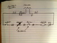
Here's what the schematic should look like for this application...
Yes - that looks alot better (& safer !)
No idea about the heat effects from the rheostat though - and would also be interesting to hear if that type of design worked ok for the application in question. (torque issues and/or current draw issues ? [blowing fuses / tripping breakers])
As one poster already suggested - get ur hands on a variable speed drill & use a footswitch - should be alot less safety issues and better functionality that way also methinks ?
Good luck & be safe !
Cheers.
Let me just say that asking AZ is asking for trouble.
I've built dozens of specially wired AC custom equipment as part of my career. My advice: don't do this. You're basically asking if it's okay to build a shorting switch with common household components. It's the "it looks like a plug" that's thr problem.
Put the switch inline please. And use one that is rated for the power you plan to run through it. Don't use anything that looks like common plugs and outlets as a makeshift relay. Might as well just use a relay.
Freddie <~~~ professionally speaking
Here's what the schematic should look like for this application...
I agree with Hungarian and Freddie. Reasons:
1. the outlet's engineered purpose (to supply power at both outlets for devices) is being jury-rigged to do something else. Yes, there is a tab on each side that you can break/snap off to isolate each outlet, but that is so one outlet can be used with a wall light switch for a lamp.
2. the hot/neutral dedication to task of the outlet is being overridden (i.e. you'll notice that the vertical slots on an outlet are different -- one slot is bigger/longer than the other, with the shorter vertical slot for the hot and the longer vertical slot for the neutral). In the proposal above, the slot that's supposed to be for neutral is in fact a hot return. Outlets are made for just that -- to supply "out" and not be a return.
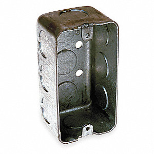
Instead of reengineering an outlet to make the components fit (roughly analogous to making the house fit the door), I agree with Hungarian's schematic -- rework the components to work properly, in series with each other. You'll find that you'll have to cut the AC plugs from the foot pedal, the rheostat, and the drill to do this. What you can do, is to get yourself a separate electrical box with cable clamp connectors to do this wiring:
1. A "handy box" like the following:
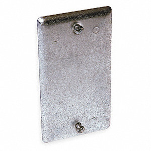
2. Handy box cover:
3. Cable clamp connectors (these go in the "knockouts" on the sides of the handy box -- the knockouts are tapped out with your palm on the back of a screwdriver):
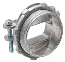
(You'll need four [4] of the cable clamp connectors: 1 for the rheostat, 1 for the foot pedal, 1 for the drill, and one for the AC plug that will go to a standard outlet.)
- Obviously, you'll need some wire nuts and some wire strippers.
- Cut-off the AC plugs from the rheostat and foot pedal to leave as much cord connected to those devices as you need -- they will need to reach the handy box.
- Wire it up according to Hungarian's diagram.
- Remember, do not interrupt the neutral from the AC plug to the drill; install all of the devices (rheostat, foot pedal) in series with the hot wire.
- Make sure to use a grounded/3-wire cable from the AC plug to the handy box -- you're going to be connecting that green ground to the grounding screw found inside the handy box.
- And, if the rheostat and foot pedal use 3-wire cable (it appears the rheostat does from the picture above), make sure you also connect those ground wires to the handy box's grounding screw. (You might consider using a single short section of ground wire to the handy box's grounding screw, and wire nut that to all the green grounding wires together -- otherwise trying to fit multiple ground wires under the same screw head is going to be a pain -- and is against code, too.)
- Have an electrician check over your completed work -- unscrew one of the handy box cover's screws and swivel it to one side so the electrician can look inside the handy box to inspect your wiring.
Hope that helps!
-Sean
Last edited:
Here's what the schematic should look like for this application...
Bingo we have a winner.
First what you are trying to do isn't illegal,however I would advise hiring a qualified, licensed electrician.
What you diagrammed would work however its not advised. You would be better served removing the receptacle, adding a box extension onto the wall box, then hard wiring a fusible safety switch. Come off the load side of the safety switch to another (4*4) box where the connections could then be made for your equipment. This would be the safest way to for what you have in mind. You need to check you equipment and install fuses rated for the LOWEST FLA (full load amp), but should be no larger than 15 amps, the smaller the better.
Let me just say that asking AZ is asking for trouble.
I've built dozens of specially wired AC custom equipment as part of my career. My advice: don't do this. You're basically asking if it's okay to build a shorting switch with common household components. It's the "it looks like a plug" that's thr problem.
Put the switch inline please. And use one that is rated for the power you plan to run through it. Don't use anything that looks like common plugs and outlets as a makeshift relay. Might as well just use a relay.
Freddie <~~~ professionally speaking
With your experiance, here's a thought. The foot pedal for a sewing machine, looks to me like a straight 110v in and 110v out, without any voltage convertion taking place through the peddle. You would also be able to compare the amp rating of the sew. machine motor and the drill motor. You would only have to change the plug that fits into the sewing machine motor to a common two wire female plug. Also, you would want to use a two wire variable speed drill motor. Probably find a used sewing machine at a thrift store, cheap. Just a few thoughts ????????
Dale
Here's what the schematic should look like for this application...
I like this. Or, run the foot switch to a properly sized motor contactor and run its contact in series (replace the on/off switch, I suppose).
Freddie <~~~ oh, our sandbox, Mark
They sell sewing machine motors and pedals eBay for next to nothing.With your experiance, here's a thought. The foot pedal for a sewing machine, looks to me like a straight 110v in and 110v out, without any voltage convertion taking place through the peddle. You would also be able to compare the amp rating of the sew. machine motor and the drill motor. You would only have to change the plug that fits into the sewing machine motor to a common two wire female plug. Also, you would want to use a two wire variable speed drill motor. Probably find a used sewing machine at a thrift store, cheap. Just a few thoughts ????????
Dale
Can you hook up a similarly rated variable speed drill motor? Let me ask you... is your drill motor AC or DC? Your drill motor.
Freddie <~~~ doesn't know corded drill
They sell sewing machine motors and pedals eBay for next to nothing.
Can you hook up a similarly rated variable speed drill motor? Let me ask you... is your drill motor AC or DC? Your drill motor.
Freddie <~~~ doesn't know corded drill
sewing machine pedal are typically 1 to 2 amp load rheostats, far lower than what I'd need.
Initially I did find a variable speed rheostat foot pedal on ebay and was using it for a while. It was rated at 6 amps .. (that's hard to find) and that finally shit the bed. A 15 amp foot rheostat is very expensive that's why I went with the momentary on / off foot pedal for 18 bucks and the hand controlled 15amp rheostat for 25 bucks.
Also, if I wanted to hard wire this it wouldn't have to be such a crazy modification. I just use this lathe so little I don't want all this stuff connected all the time. I think I'll look into twist lock plugs to prevent anyone from plugging into the outlet. Thing is ... even if they did .. it's no short... it's just a couple of open circuits and the appliance or tool simply wouldn't work.
Last edited:
The Engineer in me says....please don't do this. If you can't properly diagram this or don't know whether it will work you are not qualified to do this. How would you feel if you hurt yourself or someone else all in the name of saving a few bucks? Find a friend or pay someone.
An improper ground or wiring mistake can ruin a day or someone's life. Arc flashes occur in milliseconds. You would be amazed how much energy is a behind a 15Amp circuit.
https://www.youtube.com/watch?v=Hp1JdVwbN_U
Nick
Holy moley! Can that kind of blast occur in a 220V residential panel?
Holy moley! Can that kind of blast occur in a 220V residential panel?
Here's a link to some 220 arc flashes.
https://www.google.com/search?q=220...www.nachi.org%2Farc-flash-dangers.htm;595;335
An arc flash (also known as arc blast) is a sudden, explosive electrical arc that results from a short circuit through air. The air in the vicinity of an arc flash is heated to between 5,000 and 35,000 degrees in no more than 1/1000 of a second, becoming an electrically-conductive plasma. The sudden heating can cause a shock wave blast equivalent to several sticks of dynamite and carrying vaporized metal and shrapnel.
Last edited: