Squirt. End Mass and Cue Flexibility.

LAMas

AzB Silver Member
Silver Member
I am with Fred on this one.... "while tip and ball are in contact" also means that at slower speeds where contact time varies by tip hardness the tip also has an impact on squirt as it is a main factor in how long the tip stays on the ball.... Is it any wonder that there are so many different shafts and tips on the market if there is a synergistic possibility??

Now does swooping have the same effect as a flexible shaft on the deflection equation and would it have different effects based on different stiffness shafts? Sorry had to do it......

Now you did it.

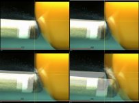
Does moving the tip slightly away from the CB with the back hand during contact as the tip is following the CB's rotation...:smile:

4 pics.jpg

Be well
 

dr_dave

Instructional Author
Gold Member
Silver Member
This has been one of the most interesting threads of its kind to follow, congrats and thanks to everyone contributing, would it be possible that someone summarizes the most serious "conclusions" of this discussion in a post, everything worthy of mentioning, even if some contradict some other?
FYI, I have been summarizing all along on the squirt endmass and stiffness effects resource page. Most of the info is a summary of the posts I have made (edited for accuracy), but the page also includes contributions and insightful quotes from others.

Enjoy,
Dave
 

dr_dave

Instructional Author
Gold Member
Silver Member
What Dave should do is provide scientific testing for all of the cue manufacturers. :D There might be a few that would take him up on his offer.
I would if I still had the cue testing machine we designed and built, but I don't. Maybe when I retire from my "day job," I'll consider setting up a cue-testing Lab and offer to test and post results for any cues any manufacturer wants to send me (for a fee, of course).

Regardless, there is already a fairly large amount of data already available here:

published squirt and pivot-length data for a large number of shafts

And if anyone (including manufacturers) wants to test and compare shafts on there own, even if they don't have a cue testing machine, the procedure described and documented on the cue natural-pivot-length resource page works fairly well, and the results can be compared to data already published for other shafts. Personally, I think every cue manufacturer should be required to publish (and even mark on the shaft) the natural pivot length of the shaft. That way, customers could make a more-educated decision when considering what to purchase.

Regards,
Dave
 

Petros Andrikop

AzB Silver Member
Silver Member
FYI, I have been summarizing all along on the squirt endmass and stiffness effects resource page. Most of the info is a summary of the posts I have made (edited for accuracy), but the page also includes contributions and insightful quotes from others.

Enjoy,
Dave

Thanks for replying Dave, I've been following your great work, I was just wondering if we could have a summary of the "conclusions" (at least some of them) placed here in this thread, basically a list of those commonly accepted and the few that "contradict" each other. That is, if there is any "common ground" coming out of this discussion, even upon disagreement.
Thanks again.
Petros
 

Jal

AzB Silver Member
Silver Member
Earlier I said:

If this is the situation described by your example (Dr. Dave's):

]///////////(mass 1)<----- Force----->(mass 2)

then the force is pushing on the wall behind the spring besides compressing it. Without the wall (the support), there is no compression. So the analogous "endmass" here is mass1 plus the wall plus whatever it's attached to.

Why not? Isn't the compression felt even before the speed of sound in the spring has reached the wall? Isn't that in fact what we model when we say that the transverse wave hasn't reached the bridge hand yet?
Hi Corwyn,

Sorry for the delay! I was just referring to the spring as a "massless" conveyer of any momentum of mass 1 toward the wall. My point was that the wall should be included as a part of the "endmass" in my analogy. In other words, for the tip-cueball collision, any part of the shaft that gets pushed to the side should be deemed as 'endmass.' As such, there are no forces acting laterally on the cueball (i.e., restoration forces) that aren't attributable solely to the displacement (momentum) of that endmass. However...

Dr. Dave has been arguing, as illustrated by TP B.19, that the sideway's forces on the cueball stem from both endmass and the cue's stiffness (restoration forces), although the latter are relatively small. This was the source of our disagreement.

First though, as an aside, one thing you really have to like about Dr. Dave is that he never throws his authority at you. He brooks arguments and even solicits critiques of his work from those of us with only a tiny fraction of his education. He treats you essentially as if you are his peer.

He called me a few days back explaining his position, which, I'm afraid, only half-registered and which was subsequently dismissed by me as I reverted to the view indicated above (it's all endmass!) But then he very patiently tried once more and, finally, it's begun to sink in. This is my understanding of the conversation and I hope I'm not distorting his words (too much :)).

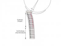
As the transverse (shear) wave travels down the shaft, it has to be reflected back off the medium in which it's propagating and reach the tip again in order to be felt by the cueball. If you divide the shaft into thin sections, when the wave reaches an interface between two sections, the leading section first transmits the shear force to the trailing section. The trailing section then, naturally (Newton's Third), produces a reaction force, equal an opposite, which then travels as a wave (disturbance) back toward the tip. Here's sort of an illustration with the black arrows indicating the original shear and the red ones indicating the reactions.

Endmass.jpg

Note: Maybe I should have reversed the locations of the black and red arrows in each section for better clarity.

As you get farther down the shaft, there isn't enough time for the reflected waves to return all the way to the tip. This is indicated by the pale red arrows. However, in this region, the sections are 1) moving to the left (have momentum), and 2) the reaction forces they're generating, while not reaching the tip, are slowing down the upper section whose reaction forces are reaching the tip.

Therefore, since we define "endmass" to be the mass that, from being pushed aside, produces a counter-force that acts on the cueball, only the upper section fits the bill. It (the upper section), being slowed by the reaction forces from the lower section, does not posses all the equal-and-opposite momentum of the cueball - the lower section carries part of it. Thus, there must be more force acting on the cueball than we can account for from the endmass (proper) alone. That force must be the restorative (flexing) force generated by the bend, since the lower section can't contribute - its waves never reach the tip.

Well, I hope I have that right, at least in spirit, and want to heartily thank Dr. Dave for taking the time to go through this with me several times!

Jim
 
Last edited:

dr_dave

Instructional Author
Gold Member
Silver Member
I'm sure of two things. One is that given the fact that the forces involved are all internal to the cue-cueball system, lateral momentum must be conserved during every moment of the collision (i.e., = 0 for a straight stroke). Second is that you know that (and know it far better than me, given everything).

If you can construct a scenario where a force is acting on the cueball that is not acting equally and opposite on the endmass, I think, well, I won't know what to think. It's true that a flex force does act on the cueball, but in acting equally and opposite on the endmass, it acts in the opposite direction of what our intuition suggests, which would be to push the endmass in the same direction as the cueball.
Jim,

I finally found time to construct the new diagram and create some explanation to go with it. It is in the answer to the fifth question on the squirt endmass and stiffness effects resource page. Here's a pertinent quote that I think helps reconcile your previous objections with my analysis:

The forward impulse (F_imp) on the CB is:

F_imp = m_ball*v_fwd​

where m_ball is the mass of the CB and v_fwd is the forward speed of the CB.

For a given squirt angle "α," the sideways impulse (S_imp) acting on the CB, which acts equal and opposite on the tip, is:

S_imp = F_imp*tan(α) = m_ball*v_side ................. (1)​

where v_side is the sideways speed of the CB.

The "effective endmass" feels this impulse, but it also feels an impulse resulting from a shear force resisting shaft bending because the flexed shaft is pushing back on the endmass (and an equal and opposite force is felt on the remainder of the cue). This is illustrated in the following diagram. The "effective endmass" of the shaft involves only the 5-8 inches of the shaft closest to the tip. It flexes and acquires momentum during impact. However, the transverse or lateral or shear elastic wave travels farther down the shaft during tip contact (10-16 inches) since the elastic wave must travel to and back from mass for it to be "felt" by the tip during contact. Therefore, a portion of the cue beyond the endmass is also flexed and also acquires some momentum during tip contact.

squirt_flex_effect.jpg

The momentum balance equation for the whole system is:

m_ball*v_side = m_end*v_end + m_beyond*v_beyond​

where m_end is the effective endmass of the shaft, v_end is the effective speed developed by the endmass, m_beyond is the effective mass of the flexed portion of the shaft beyond the endmass, and v_beyond is the effective speed developed by this mass. Note that in a typical simplified analysis of squirt and endmass (e.g., in TP A.31), the flex effect is neglected, resulting in a slightly larger effective endmass. Here, because some of the CB sideways momentum (m_ball*v_side) is offset by the momentum beyond the endmass (m_beyond*v_beyond), the endmass will have slightly less momentum (and therefore a slightly less effective endmass than in the simplified analysis).

The proper momentum equation for the endmass, taking into account the shaft-flex effect, is:

S_imp - FL_imp = m_end*v_end .................... (2)​

where FL_imp is the impulse of the force associated with the flex of the shaft acting on the endmass (and equal and opposite on the portion of the shaft beyond the endmass) during tip contact with the CB.

Substituting S_imp from Equation 1 into Equation 2 gives:

m_ball*v_side = m_end*v_end + FL_imp​

Therefore, it is clear that the CB's sideways momentum comes from two effects: the momentum transfer from the endmass (m_end*v_end) and the impulse of the flex force (FL_imp). Effective endmass is affected by lateral or transverse stiffness (as described in the main section above), but force due to flexing is a separate effect. This is clear because you can have one without the other. If most of the endmass were in the tip and ferrule, and the shaft had little or no stiffness (i.e., if it took little or no force to flex the shaft), there would still be the "m_end*v_end" effect but little or no FL_imp effect. And if the shaft end were stiff laterally but had negligible endmass (even though a greater length of the shaft would contribute to endmass), there would still be a "FL_imp" effect but little or no "m_end*v_end" effect. When the CB pushes sideways on the tip, it creates endmass momentum, but it also flexes the cue. Both of these things require force, hence the two terms in the equation above.


Regards,
Dave
 

dr_dave

Instructional Author
Gold Member
Silver Member
Dr. Dave has been arguing, as illustrated by TP B.19, that the sideway's forces on the cueball stem from both endmass and the cue's stiffness (restoration forces), although the latter are relatively small. This was the source of our disagreement.

First though, as an aside, one thing you really have to like about Dr. Dave is that he never throws his authority at you. He brooks arguments and even solicits critiques of his work from those of us with only a tiny fraction of his education. He treats you essentially as if you are his peer.

He called me a few days back explaining his position, which, I'm afraid, only half-registered and which was subsequently dismissed by me as I reverted to the view indicated above (it's all endmass!) But then he very patiently tried once more and, finally, it's begun to sink in. This is my understanding of the conversation and I hope I'm not distorting his words (too much :)).
Jim,

Thank you for your graciousness and for accepting my explanation, despite your recent disagreements. This level of maturity is refreshing to see on AZB. There are certainly a few users out there who can learn a lesson from your example.


As the transverse (shear) wave travels down the shaft, it has to be reflected back off the medium in which it's propagating and reach the tip again in order to be felt by the cueball. If you divide the shaft into thin sections, when the wave reaches an interface between two sections, the leading section first transmits the shear force to the trailing section. The trailing section then, naturally (Newton's Third), produces a reaction force, equal an opposite, which then travels as a wave (disturbance) back toward the tip. Here's sort of an illustration with the black arrows indicating the original shear and the red ones indicating the reactions.

View attachment 410832

Note: Maybe I should have reversed the locations of the black and red arrows in each section for better clarity.

As you get farther down the shaft, there isn't enough time for the reflected waves to return all the way to the tip. This is indicated by the pale red arrows. However, in this region, the sections are 1) moving to the left (have momentum), and 2) the reaction forces they're generating, while not reaching the tip, are slowing down the upper section whose reaction forces are reaching the tip.

Therefore, since we define "endmass" to be the mass that, from being pushed aside, produces a counter-force that acts on the cueball, only the upper section fits the bill. It (the upper section), being slowed by the reaction forces from the lower section, does not posses all the equal-and-opposite momentum of the cueball - the lower section carries part of it. Thus, there must be more force acting on the cueball than we can account for from the endmass (proper) alone. That force must be the restorative (flexing) force generated by the bend, since the lower section can't contribute - its waves never reach the tip.
Excellent explanation and diagram. You must have been composing this the same time I was putting together my recent post (with my new diagram that nicely complements yours), but you beat me to the punch by a few minutes.

FYI, I just added a quote of your post on the squirt endmass and stiffness effects resource page.


Well, I hope I have that right, at least in spirit
Again, your explanation and diagram are excellent.

want to heartily thank Dr. Dave for taking the time to go through this with me several times!
You're very welcome. I want to thank you too for helping me think through this stuff at a deeper level than I have in the past. That's saying a lot, because I have spent countless hours researching, analyzing, experimenting, and filming squirt-related effects for many, many years.

Best regards,
Dave

PS: It is refreshing to see threads like this again on AZB. That's too bad PJ got himself banned again (although, he earned it), because he is always a good contributor in these sorts of threads (when he isn't being dragged into the mud by users not quite as mature as you).
 

LAMas

AzB Silver Member
Silver Member
I am happy to have started this thread to answer a question that has lingered for years without mature equations to back up the word descriptions.:smile:

Be well.
 

LAMas

AzB Silver Member
Silver Member
Earlier I said:

If this is the situation described by your example (Dr. Dave's):

]///////////(mass 1)<----- Force----->(mass 2)

then the force is pushing on the wall behind the spring besides compressing it. Without the wall (the support), there is no compression. So the analogous "endmass" here is mass1 plus the wall plus whatever it's attached to.

Hi Corwyn,

Sorry for the delay! I was just referring to the spring as a "massless" conveyer of any momentum of mass 1 toward the wall. My point was that the wall should be included as a part of the "endmass" in my analogy. In other words, for the tip-cueball collision, any part of the shaft that gets pushed to the side should be deemed as 'endmass.' As such, there are no forces acting laterally on the cueball (i.e., restoration forces) that aren't attributable solely to the displacement (momentum) of that endmass. However...

Dr. Dave has been arguing, as illustrated by TP B.19, that the sideway's forces on the cueball stem from both endmass and the cue's stiffness (restoration forces), although the latter are relatively small. This was the source of our disagreement.

First though, as an aside, one thing you really have to like about Dr. Dave is that he never throws his authority at you. He brooks arguments and even solicits critiques of his work from those of us with only a tiny fraction of his education. He treats you essentially as if you are his peer.

He called me a few days back explaining his position, which, I'm afraid, only half-registered and which was subsequently dismissed by me as I reverted to the view indicated above (it's all endmass!) But then he very patiently tried once more and, finally, it's begun to sink in. This is my understanding of the conversation and I hope I'm not distorting his words (too much :)).

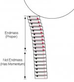
As the transverse (shear) wave travels down the shaft, it has to be reflected back off the medium in which it's propagating and reach the tip again in order to be felt by the cueball. If you divide the shaft into thin sections, when the wave reaches an interface between two sections, the leading section first transmits the shear force to the trailing section. The trailing section then, naturally (Newton's Third), produces a reaction force, equal an opposite, which then travels as a wave (disturbance) back toward the tip. Here's sort of an illustration with the black arrows indicating the original shear and the red ones indicating the reactions.

View attachment 410832

Note: Maybe I should have reversed the locations of the black and red arrows in each section for better clarity.

As you get farther down the shaft, there isn't enough time for the reflected waves to return all the way to the tip. This is indicated by the pale red arrows. However, in this region, the sections are 1) moving to the left (have momentum), and 2) the reaction forces they're generating, while not reaching the tip, are slowing down the upper section whose reaction forces are reaching the tip.

Therefore, since we define "endmass" to be the mass that, from being pushed aside, produces a counter-force that acts on the cueball, only the upper section fits the bill. It (the upper section), being slowed by the reaction forces from the lower section, does not posses all the equal-and-opposite momentum of the cueball - the lower section carries part of it. Thus, there must be more force acting on the cueball than we can account for from the endmass (proper) alone. That force must be the restorative (flexing) force generated by the bend, since the lower section can't contribute - its waves never reach the tip.

Well, I hope I have that right, at least in spirit, and want to heartily thank Dr. Dave for taking the time to go through this with me several times!

Jim
Jim,
Great illustration.

Now the but.
Would these lateral forces follow the CB forward as it rotates until release?

You could add more rectangles with red and black arrows on top of the last one that follow the surface of the CB as it rotates until there is no longer contact after ~2 milliseconds?:wink:

Thanks for your inquiring mind...like others have.:thumbup:

Be well
 

Jal

AzB Silver Member
Silver Member
Jim,

I finally found time to construct the new diagram and create some explanation to go with it. It is in the answer to the fifth question on the squirt endmass and stiffness effects resource page. Here's a pertinent quote that I think helps reconcile your previous objections with my analysis:

The forward impulse (F_imp) on the CB is:

F_imp = m_ball*v_fwd​

where m_ball is the mass of the CB and v_fwd is the forward speed of the CB.

For a given squirt angle "α," the sideways impulse (S_imp) acting on the CB, which acts equal and opposite on the tip, is:

S_imp = F_imp*tan(α) = m_ball*v_side ................. (1)​

where v_side is the sideways speed of the CB.

The "effective endmass" feels this impulse, but it also feels an impulse resulting from a shear force resisting shaft bending because the flexed shaft is pushing back on the endmass (and an equal and opposite force is felt on the remainder of the cue). This is illustrated in the following diagram. The "effective endmass" of the shaft involves only the 5-8 inches of the shaft closest to the tip. It flexes and acquires momentum during impact. However, the transverse or lateral or shear elastic wave travels farther down the shaft during tip contact (10-16 inches) since the elastic wave must travel to and back from mass for it to be "felt" by the tip during contact. Therefore, a portion of the cue beyond the endmass is also flexed and also acquires some momentum during tip contact.

squirt_flex_effect.jpg

The momentum balance equation for the whole system is:

m_ball*v_side = m_end*v_end + m_beyond*v_beyond​

where m_end is the effective endmass of the shaft, v_end is the effective speed developed by the endmass, m_beyond is the effective mass of the flexed portion of the shaft beyond the endmass, and v_beyond is the effective speed developed by this mass. Note that in a typical simplified analysis of squirt and endmass (e.g., in TP A.31), the flex effect is neglected, resulting in a slightly larger effective endmass. Here, because some of the CB sideways momentum (m_ball*v_side) is offset by the momentum beyond the endmass (m_beyond*v_beyond), the endmass will have slightly less momentum (and therefore a slightly less effective endmass than in the simplified analysis).

The proper momentum equation for the endmass, taking into account the shaft-flex effect, is:

S_imp - FL_imp = m_end*v_end .................... (2)​

where FL_imp is the impulse of the force associated with the flex of the shaft acting on the endmass (and equal and opposite on the portion of the shaft beyond the endmass) during tip contact with the CB.

Substituting S_imp from Equation 1 into Equation 2 gives:

m_ball*v_side = m_end*v_end + FL_imp​

Therefore, it is clear that the CB's sideways momentum comes from two effects: the momentum transfer from the endmass (m_end*v_end) and the impulse of the flex force (FL_imp). Effective endmass is affected by lateral or transverse stiffness (as described in the main section above), but force due to flexing is a separate effect. This is clear because you can have one without the other. If most of the endmass were in the tip and ferrule, and the shaft had little or no stiffness (i.e., if it took little or no force to flex the shaft), there would still be the "m_end*v_end" effect but little or no FL_imp effect. And if the shaft end were stiff laterally but had negligible endmass (even though a greater length of the shaft would contribute to endmass), there would still be a "FL_imp" effect but little or no "m_end*v_end" effect. When the CB pushes sideways on the tip, it creates endmass momentum, but it also flexes the cue. Both of these things require force, hence the two terms in the equation above.


Regards,
Dave
Dr. Dave,

And another thanks for taking yet more time to put it down in black and white. Apparently I did absorb something from your painstaking efforts to enlighten. This is, imo, a pretty subtle phenomena and few of us, I think, would have come to it ourselves...certainly not me.

As always, thanks too for your very generous words. While many here obviously appreciate the volume, quality and reliability of your work, you probably don't get the accolades you fully deserve, not even from me. I'll try to change, perhaps, but please keep in mind that, if only silently, we do understand how fortunate we are to have your contributions.

Jim
 

Jal

AzB Silver Member
Silver Member
Jim,
Great illustration.

Now the but.
Would these lateral forces follow the CB forward as it rotates until release?

You could add more rectangles with red and black arrows on top of the last one that follow the surface of the CB as it rotates until there is no longer contact after ~2 milliseconds?:wink:

Thanks for your inquiring mind...like others have.:thumbup:

Be well
Thanks Lamas. It looks like your original instincts were correct and I apologize for trying to derail them. Good insight on your part!

Yes, the lateral forces should still be there, although, of course, evolving with time as the CB picks up rotation. The details are beyond me, for the most part.

If it's not a matter of graven importance, I'd rather not alter the pic based on two considerations: the issue has been settled, methinks, and, more importantly, laziness. But if you think it would clear anything up, maybe I could overcome my own inertia.

Jim
 

LAMas

AzB Silver Member
Silver Member
Thanks Lamas. It looks like your original instincts were correct and I apologize for trying to derail them. Good insight on your part!

Yes, the lateral forces should still be there, although, of course, evolving with time as the CB picks up rotation. The details are beyond me, for the most part.

If it's not a matter of graven importance, I'd rather not alter the pic based on two considerations: the issue has been settled, methinks, and, more importantly, laziness. But if you think it would clear anything up, maybe I could overcome my own inertia.

Jim


Jim,

You have done enough and deserve to dither.:smile:

Kinda like this.

deflection 1.jpg

Be well
 

The Renfro

Outsville.com
Silver Member
Jim,

You have done enough and deserve to dither.:smile:

Kinda like this.

View attachment 410864

Be well

Actually that's just the partial next frame and you know it.... as long as your tip is not acting like it's a solid because of max compression from high speed testing =P... I think that the mass at contact and a solid connection will hold the tip and shaft more online than in the diagram during contact if the stiffness allows... Blackboar and their LD ferruleless shafts opened my eyes to what a tip can really accomplish in the deflection equation.....
 
Last edited:

askalf

Registered
The photo of the broken cue (produced by OB Cues Co.) with a rubber plait in a shaft was published on the WEB few years ago:

https://www.pooldawg.com/article/assests/broken-obshaft-1.jpg

According to the manufacturer, this rubber plait is intended to reduce the cue vibrations.
I think that the representatives of OB Cues Company showed a little guile.
It’s known that it’s difficult to change the rubber volume (rubber is virtually incompressible –
as well as liquids), but it is easy to change a form.
Therefore, having placed a rubber plait into the closed volume, manufacturers could reduce the shaft’s transverse stiffness while preserving a longitudinal stiffness.
As a rubber density is comparable to a wood density, the reduction of squirt effect happened due to reduction of transverse stiffness only.

Sorry for my bad english
 

ENGLISH!

Banned
Silver Member
Jim,

You have done enough and deserve to dither.:smile:

Kinda like this.

View attachment 410864

Be well

attachment.php


Good Morning E,

If the red & black force vectors represented a flexible spring...

like the old screen door type...

& it was NOT stretched out, but instead 'compressed' upon itself...

& it was traveling like an arrow heading up in the diagram toward the ball...

& the right SIDE of it met the resistance of the ball...

while the left SIDE met no resistance...

would the flexible spring not first bow OUT to the left first before 'recoiling' & then 'waffling' in as it bounces off (deflects) to the left...

especially if the 'tip' of the spring had a chalked leather tip on the end to provide friction & 'grab'?

Best 2 Ya & Stay Well,
Rick
 
Last edited:

ENGLISH!

Banned
Silver Member
I am with Fred on this one.... "while tip and ball are in contact" also means that at slower speeds where contact time varies by tip hardness the tip also has an impact on squirt as it is a main factor in how long the tip stays on the ball.... Is it any wonder that there are so many different shafts and tips on the market if there is a synergistic possibility??

Now does swooping have the same effect as a flexible shaft on the deflection equation and would it have different effects based on different stiffness shafts? Sorry had to do it......

squirt_flex_effect.jpg


Hi Chris.

Does a Feel Player, that might employ a swipe stroke, look at the initial line of the stick or would they 'look to' the squirt line that the ball would take... sort of looking across the cue path line, as IF one had pivoted the cue?

If we take Dr. Dave's diagram & PIN the center of the cue ball & rotate the diagram a few degrees counter clockwise so that the white squirt line is horizontally straight right & we replace the bend of the shaft with a swipe of the cue to the left...

do we not have a tip that is hitting more near to the visual center 'viewing line' of straight horizontally right & perhaps even on the right side of that viewing line & then swiping left?

Please note that I did NOT say that the shooter & his or her eyes should rotate. They stay horizontally straight left relative to the diagram.

Is that not what Ms. Crimi sort of said?

Center CB can be a relative matter depending on one's perspective & where one is looking to & envisions the 'line' that the ball will take vs the line of the cue. I think this perhaps has been an issue in some past discussions.

Does the swiping action then "relieve" some of the lateral forces of the bending shaft & produce less squirt?

Perhaps it would help if the image were rotated 90+ degrees counter clockwise & more as a shooter would view it.

Sorry, but you asked.

Best 2 Ya,
Rick
 
Last edited:

dr_dave

Instructional Author
Gold Member
Silver Member
...would the flexible spring not first bow OUT to the left first before 'recoiling' & then 'waffling' in as it bounces off (deflects) to the left...

especially if the 'tip' of the spring had a chalked leather tip on the end to provide friction & 'grab'?
FYI, I made a slight modification to my diagram and added some explanation to the squirt endmass and stiffness resource page. Here's the modified diagram:

squirt_flex_effect.jpg

and here's a pertinent quote from the resource page:

Also notice in the diagram how the tip end of the shaft also flexes back toward the CB. This is due to the off-center hit on the tip. As the tip grabs the CB, the contact forces bend the shaft end toward the CB as the CB pushes the tip and shaft away with CB rotation. This tip-end flex action is visible in the super-slow-motion videos on the cue vibration resource page, and the overall push of the endmass away from the CB is clear in the illustrations and video on the what causes squirt resource page.

This doesn't change the analysis, results, or conclusions, but the diagram is now a better illustration of the actual deformations and flex. The "effective endmass" takes into account this sort of thing (and more).

I'm not sure if this directly relates to what you are bringing up, but I thought it might.

Regards,
Dave
 

dr_dave

Instructional Author
Gold Member
Silver Member
Does the swiping action then "relieve" some of the lateral forces of the bending shaft & produce less squirt?
A swooping or swiping action does change the effective line of action of a shot slightly, but the speed of the swoop or swipe is typically small in comparison to the forward speed of the cue. Also, the speed at which the endmass momentum and flex effects take place (over the incredibly brief tip contact time) make any swooping or swiping speed insignificant in a practical sense.

For those interested, the effects of a swooping or swiping stroke are covered in detail with numerous explanations and illustrations on the swoop stroke resource page. Also included there is a carefully-designed experiment that can easily be used to demonstrate if any theories related to a swoop or swipe stroke have any practical merit.

Please don't turn this thread into what the swoop/swipe thread became before it was killed. It would be a shame if this fruitful thread were also lost for all eternity.

Regards,
Dave
 
Last edited:

ENGLISH!

Banned
Silver Member
FYI, I made a slight modification to my diagram and added some explanation to the squirt endmass and stiffness resource page. Here's the modified diagram:

squirt_flex_effect.jpg

and here's a pertinent quote from the resource page:

Also notice in the diagram how the tip end of the shaft also flexes back toward the CB. This is due to the off-center hit on the tip. As the tip grabs the CB, the contact forces bend the shaft end toward the CB as the CB pushes the tip and shaft away with CB rotation. This tip-end flex action is visible in the super-slow-motion videos on the cue vibration resource page, and the overall push of the endmass away from the CB is clear in the illustrations and video on the what causes squirt resource page.

This doesn't change the analysis, results, or conclusions, but the diagram is now a better illustration of the actual deformations and flex. The "effective endmass" takes into account this sort of thing (and more).

I'm not sure if this directly relates to what you are bringing up, but I thought it might.

Regards,
Dave

Thanks Dave,

I can't really see in the video.

My question to Lamas was with regards to the initial bend of the shaft. Is the initial very short time bend with the end angled in toward center ball with the 'mid' of the bend bowed out away from the ball...

or is that absorbed by the tip & the compression of the tip & the 'mid' shaft flex bows in, as in your diagram?

If the velocity of the shaft is met with resistance on the inside, toward center ball, would not the 'mid shaft' bow out initially? Would not that be the initial compression of the shaft until it is released & then rides 'out' & away from the ball?

Thanks in advance,

PS EDIT: Dave, Is your diagram now representing a double "S" bend of the shaft?
 
Last edited:

dr_dave

Instructional Author
Gold Member
Silver Member
Does the swiping action then "relieve" some of the lateral forces of the bending shaft & produce less squirt?
A swooping or swiping motion does produce less "apparent squirt" because the effective line of action of the shot is being changed (as with a pre-stroke BHE pivot correction). This is clear with the slightly different lines of aim required with the swoop and equivalent straight strokes in the comparison starting at the 6:34 point in the swoop stroke experiment video.

And if someone were able to swoop or swipe even faster (as compared to the forward speed of the cue), the aim and "apparent squirt" differences would be even greater.

Regards,
Dave
 
Last edited:
Top