Another full splice G-code

Graciocues

AzB Silver Member
Silver Member
I used this program today and it works great. Long points.
This one is for a 3 axis.
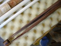
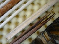
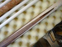
I tried the 5/8" bore hole and think 3/4" works better. With the 5/8" hole I had to draw up a second G-code to cut the tips deeper.
( Profile 2 )
( Mach2/3 Postprocessor )
N20G00G20G17G20G90G40G49G80
N30G70
N40T1M06
N50G00G43Z0.7874H1
N60S35000M03
N70G94
N80X0.0000Y0.0000F8.0
N90G00X-0.0000Y-0.0000Z0.2362
N100G01Z-0.0494F10.0
N110G01X9.5000Y0.3257F8.0
N120Y-0.3257
N130X-0.0000Y-0.0000
N140G01Z-0.0988F10.0
N150G01X9.5000Y0.3257F8.0
N160Y-0.3257
N170X-0.0000Y-0.0000
N180G01Z-0.1481F10.0
N190G01X9.5000Y0.3257F8.0
N200Y-0.3257
N210X-0.0000Y-0.0000
N220G01Z-0.1975F10.0
N230G01X9.5000Y0.3257F8.0
N240Y-0.3257
N250X-0.0000Y-0.0000
N260G01Z-0.2469F10.0
N270G01X9.5000Y0.3257F8.0
N280Y-0.3257
N290X-0.0000Y-0.0000
N300G01Z-0.2962F10.0
N310G01X9.5000Y0.3257F8.0
N320Y-0.3257
N330X-0.0000Y-0.0000
N340G01Z-0.3456F10.0
N350G01X9.5000Y0.3257F8.0
N360Y-0.3257
N370X-0.0000Y-0.0000
N380G01Z-0.3950F10.0
N390G01X9.5000Y0.3257F8.0
N400Y-0.3257
N410X-0.0000Y-0.0000
N420G01Z-0.4444F10.0
N430G01X9.5000Y0.3257F8.0
N440Y-0.3257
N450X-0.0000Y-0.0000
N460G01Z-0.4938F10.0
N470G01X9.5000Y0.3257F8.0
N480Y-0.3257
N490X-0.0000Y-0.0000
N500G01Z-0.5431F10.0
N510G01X9.5000Y0.3257F8.0
N520Y-0.3257
N530X-0.0000Y-0.0000
N540G01Z-0.5925F10.0
N550G01X9.5000Y0.3257F8.0
N560Y-0.3257
N570X-0.0000Y-0.0000
N580G01Z-0.6419F10.0
N590G01X9.5000Y0.3257F8.0
N600Y-0.3257
N610X-0.0000Y-0.0000
N620G01Z-0.6913F10.0
N630G01X9.5000Y0.3257F8.0
N640Y-0.3257
N650X-0.0000Y-0.0000
N660G01Z-0.7406F10.0
N670G01X9.5000Y0.3257F8.0
N680Y-0.3257
N690X-0.0000Y-0.0000
N700G01Z-0.7900F10.0
N710G01X9.5000Y0.3257F8.0
N720Y-0.3257
N730X-0.0000Y-0.0000
N740G00Z0.2362
N750G00Z0.7874
N760G00X0.0000Y0.0000
N770M09
N780M30
%
 

Attachments

  • 87 002.jpg
    87 002.jpg
    55.6 KB · Views: 698
..............................

This is the G-code to cut the tips deeper.
Somebody asked about the center being hollow. The points start at the same place as the bore hole ends.


( Profile 3 )
( Mach2/3 Postprocessor )
N20G00G20G17G20G90G40G49G80
N30G70
N40T1M06
N50G00G43Z0.7874H1
N60S35000M03
N70G94
N80X0.0000Y0.0000F8.0
N90G00X5.6116Y-0.1924Z0.2362
N100G01Z-0.8400F10.0
N110G01X9.5000Y-0.3257F8.0
N120G00Z0.2362
N130G00X5.6116Y-0.1924
N140G01Z-0.8900F10.0
N150G01X9.5000Y-0.3257F8.0
N160G00Z0.2362
N170G00X5.6116Y-0.1924
N180G01Z-0.9400F10.0
N190G01X9.5000Y-0.3257F8.0
N200G00Z0.2362
N210G00X5.6116Y-0.1924
N220G01Z-0.9900F10.0
N230G01X9.5000Y-0.3257F8.0
N240G00Z0.2362
N250G00X5.6116Y-0.1924
N260G01Z-1.0400F10.0
N270G01X9.5000Y-0.3257F8.0
N280G00Z0.2362
N290G00X5.6116Y-0.1924
N300G01Z-1.0900F10.0
N310G01X9.5000Y-0.3257F8.0
N320G00Z0.2362
N330G00Y0.3257
N340G01Z-0.8400F10.0
N350G01X5.6191Y0.1927F8.0
N360G00Z0.2362
N370G00X9.5000Y0.3257
N380G01Z-0.8900F10.0
N390G01X5.6191Y0.1927F8.0
N400G00Z0.2362
N410G00X9.5000Y0.3257
N420G01Z-0.9400F10.0
N430G01X5.6191Y0.1927F8.0
N440G00Z0.2362
N450G00X9.5000Y0.3257
N460G01Z-0.9900F10.0
N470G01X5.6191Y0.1927F8.0
N480G00Z0.2362
N490G00X9.5000Y0.3257
N500G01Z-1.0400F10.0
N510G01X5.6191Y0.1927F8.0
N520G00Z0.2362
N530G00X9.5000Y0.3257
N540G01Z-1.0900F10.0
N550G01X5.6191Y0.1927F8.0
N560G00Z0.2362
N570G00Z0.7874
N580G00X0.0000Y0.0000
N590M09
N600M30
%
 

Attachments

  • 87 003.jpg
    87 003.jpg
    55.3 KB · Views: 687
Graciocues said:
This is the G-code to cut the tips deeper.
Somebody asked about the center being hollow. The points start at the same place as the bore hole ends.

I think what they were asking is about the under side of the points not coming to a complete v because of the bore hole?
At least that's what I'm asking.
 
.......................

There is a gap under the points. This time I had a smaller bore hole for a smaller gap. I fill it with epoxy.
 

Attachments

  • 87 004.jpg
    87 004.jpg
    55.8 KB · Views: 670
...................

I still have a lot of work left on this because I'm going to add 4 veneers.
 

Attachments

  • 87 005.jpg
    87 005.jpg
    55.3 KB · Views: 675
g codes

Thanks for sharing these. One question, are you doing these on your Breeze CNC or a longer x-axis machine. I'm setting one up soon, so it would be helpful to know if my smaller x-axis travel will prohibit me from doing these. Thanks again.
Tom Gedris, Triple Cross Cues:cool:
 
For the under side of the points to form a V from tip to base of the point the tool must have a depth of cut at least half the diameter of the blank. Drill a hole in the blank and you have cut away part of the V.

BarenbruggeCues said:
I think what they were asking is about the under side of the points not coming to a complete v because of the bore hole?
At least that's what I'm asking.
 
TripXQ said:
Thanks for sharing these. One question, are you doing these on your Breeze CNC or a longer x-axis machine. I'm setting one up soon, so it would be helpful to know if my smaller x-axis travel will prohibit me from doing these. Thanks again.
Tom Gedris, Triple Cross Cues:cool:
tom
you should be able to do this on your machine we will work on a program for you along with other programss you will get free of charge...lee
 
TellsItLikeItIs said:
For the under side of the points to form a V from tip to base of the point the tool must have a depth of cut at least half the diameter of the blank. Drill a hole in the blank and you have cut away part of the V.

This is what I was envisioning happening................

I don't think I'm too crazy about trying to make sure that void is filled with glue during the assembling process. I haven't been able to draw it up yet and find out how much void there would be, that's why I was asking.
If the cutter length isn't sufficient to get it done with a 5/8 bore hole then I would do a program where you may have a step bore to get the job done without destroying the underside of the points.
Again, not having drawn it yet, this may be a moot point not knowing exactly how much of the underside is missing.
 
Actually what I should have said is Drill a hole in the blank larger than the planned space between the points and you have cut away part of the V.

Im not real fond of filling a void like that I cant see with epoxy. How would you know its actually filled without xray.

Just a point of interest but this can be done on a manual mill also. Ive been dialing in my fixture for almost 2 months now between jobs. In the time its taken me to get almost there I could have built 10 jigs for the band saw or table saw. Sometimes the easy way isnt the easiest way.

BarenbruggeCues said:
This is what I was envisioning happening................

I don't think I'm too crazy about trying to make sure that void is filled with glue during the assembling process. I haven't been able to draw it up yet and find out how much void there would be, that's why I was asking.
If the cutter length isn't sufficient to get it done with a 5/8 bore hole then I would do a program where you may have a step bore to get the job done without destroying the underside of the points.
Again, not having drawn it yet, this may be a moot point not knowing exactly how much of the underside is missing.
 
BarenbruggeCues said:
I think what they were asking is about the under side of the points not coming to a complete v because of the bore hole?
At least that's what I'm asking.

Yes, that was me and that is what appeared to be the case as I pictured it as well.
 
All this talk of CNC milling full splice cues got me back excited about building full splice cues. I cut a forearm on the CNC and used my band saw to cut the handle yesterday. Turned it down today. I carried the points 11 inches long. I held it up next to one of the purhcased blanks and mine looks much better. I did not like my angle on how my jigs were set up before. They gave short points like the blanks that are commonly available. So yesterday I cut a forearm like I wanted then re-set my handle fixture up for longer points and this one came out the best I have ever made one.
 
cueman said:
All this talk of CNC milling full splice cues got me back excited about building full splice cues. I cut a forearm on the CNC and used my band saw to cut the handle yesterday. Turned it down today. I carried the points 11 inches long. I held it up next to one of the purhcased blanks and mine looks much better. I did not like my angle on how my jigs were set up before. They gave short points like the blanks that are commonly available. So yesterday I cut a forearm like I wanted then re-set my handle fixture up for longer points and this one came out the best I have ever made one.


Good for you Chris........I think this discussion has sparked a new flame in few.
 
This is the third full splice I've built on my CNC. The first two I used a 3/4" bore hole. This time I tried a 5/8" hole and like the results better with the void being smaller. The problem is the bit isn't long enough. I had to make another program to finish the tips. When I find a longer bit the bore hole won't be needed.
If you want to add more work to the build a person could bore in several sizes. Stepping the size down the deeper the hole gets. In a perfect world a cone shaped hole would work the best.

Lee was nice and gave everybody a free program. Somebody asked If I'd share mine and I did. For those who want to try it have fun.
 
Last edited:
Sparking interests

Make that several of us!!!!!!!!!!!!!!!!! This set of exchanges of info is the way a forum should be used. People helping people with similar interests with no malice involved. It has been a pleasure hearing from you folks.
Thanks again.
Tom Gedris, Triple Cross Cues:cool:
 
cueman said:
All this talk of CNC milling full splice cues got me back excited about building full splice cues. I cut a forearm on the CNC and used my band saw to cut the handle yesterday. Turned it down today. I carried the points 11 inches long. I held it up next to one of the purhcased blanks and mine looks much better. I did not like my angle on how my jigs were set up before. They gave short points like the blanks that are commonly available. So yesterday I cut a forearm like I wanted then re-set my handle fixture up for longer points and this one came out the best I have ever made one.

Congrats Chris on your new jig. It would be kewl to see Hightower full splice blanks on the market. Are you planning on selling finished cues or selling the blanks?
 
Graciocues said:
Congrats Chris on your new jig. It would be kewl to see Hightower full splice blanks on the market. Are you planning on selling finished cues or selling the blanks?
Chris love to see some pictures and scott more pictures from you also
any new cues ? i agree go to see postive talk on here helping on another is a great thing theres plenty of business for everyone
 
In about a month or so i will get everyone full details on how I decided to make a full splice blank, I have not built a cue yet, but have been gathering some machinery, and talked to Lee, regarding how I would make them on a CNC, but another idea that just came into my head is this, once you cut the blank out and you are left with your radius that needs cleaned, make up a block the shape you need to finish the points with, and attached some sand paper, better way would be to make a file the correct shape, now all you have to do is attach the file to your Z axis where your router would go line it up and write a program, that will make your Z axis go up and down, and move in x .001 at a time of each complete revoultion of the Z axis, and you should be able to have your CNC machine file it out perfectly for you, this technique is also known as rotary broaching good luck guys

Mark
 
Graciocues said:
This is the third full splice I've built on my CNC. The first two I used a 3/4" bore hole. This time I tried a 5/8" hole and like the results better with the void being smaller.
The problem is the bit isn't long enough.
There are some companies that will build you what ever you want in a cutting bit...if it's out of their specs, they won't guarantee them, but they'll build them.
I had to make another program to finish the tips. When I find a longer bit the bore hole won't be needed.
If you want to add more work to the build a person could bore in several sizes. Stepping the size down the deeper the hole gets.
In a perfect world a cone shaped hole would work the best.
Very good idea........a tapered drill could be easily made for this. I believe perfect blanks are the end goal no matter what has to be done to achieve this.

Lee was nice and gave everybody a free program. Somebody asked If I'd share mine and I did. For those who want to try it have fun.
If it doesn't fit your needs build your own.
I detect you may feel like some are picking on you by this statement. I don't think anyone feels ungrateful that you have helped forge a path and have involved yourself in a discussion about full splice cuts. I believe this discussion will lead to perhaps a better built blank. Many times when building a new fixture, I end up revising it a minimum of 3 or 4 times before I'm happy with the end result.
..................
 
My words were harsh and I erased those words from my post after I reading it. I did go on defence. I don't have a lot of extra time and my answers are short and to the point. Please don't take them the wrong way. I don't want people to get scared and not try. Don't overthink it, try it.
I can't wait to here the feedback after some experiment with the ideas. The more people playing with it the better it will get. My technique has changed everytime. Trial and error.
 
Back
Top