CNC Linearity Problem - How to Troubleshoot?

GBCues

Damn, still .002 TIR!
Gold Member
Silver Member
Hey Guys!!

I recently rebuilt my CNC Taper attachment on my lathe in hopes of making it more accurate, but it has gotten worse, not better, so I thought I would query the collective wisdom here for some ideas.

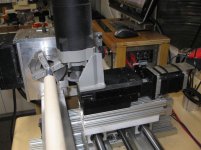
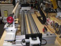
Previously, I had used unsupported 20mm bars for the long axis tracking (X in my setup) of the router. I replaced those with supported 20mm bars - they seem stiffer than stiff, with the added stiffness of mounting them on some 8020 stock (see pictures below).

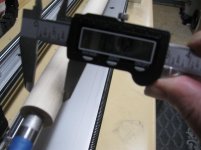
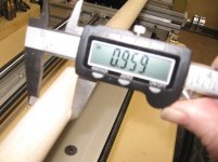
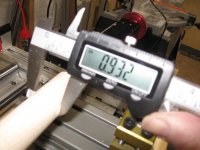
So my problem is pretty simple - you can see from the pictures below that I've got a bow in the middle of the dowel that I am trimming down in order to tune this thing in. I expected a conical taper, but not a bow.

Any ideas on where to start?

Technical info follows:

Up at the headstock, I am getting a diameter of .912 (hard to read). Then it swells to .959 near the center and finally shrinks down to .932 at the tailstock.

Feedrate is 8 ipm along the X, and my router speed is set to 7 out of 10 on my speed control (yellow box).

I am getting a pretty nice smooth cut, no signs of barber-poling.

Controller is a Gecko G540, software is Mach3, and my GCode looks like this:

N1 (Straight end to end Modified for Diameter)
N2 G01 x 0.05 F10
N3 G01 Y 0.925 F5
N4 G01 X 30.25 F8
N5 G01 Y 1.5
N6 G01 X 0.5 F25
N7 G00 F1
N8 G01 X 0.05 F5
N9 G01 Y 0.920 F5
N10 G01 X 30.25 F8
N11 G01 Y 1.5
N12 G01 X 0.5 F25
N13 G00 F1

Thanks in advance for any insight!!

Gary
 

Attachments
  • IMG_0886.jpg
    IMG_0886.jpg
    96.6 KB · Views: 805
  • IMG_0887.jpg
    IMG_0887.jpg
    93.3 KB · Views: 680
  • IMG_0888.jpg
    IMG_0888.jpg
    86.6 KB · Views: 871
  • IMG_0889.jpg
    IMG_0889.jpg
    85.1 KB · Views: 779
  • IMG_0891.jpg
    IMG_0891.jpg
    85.6 KB · Views: 811
Last edited:
cnc

How did you set up your new supported rails and how did you check their
straightness before installing.
 
I don't know how heavy your first pass is, but only taking .005" on the finish pass is probably not enough to clean it up well. Thats only .0025" per side. I'd think maybe .010-.015 per side would give a better finish, since .0025 can't get below the rough cut.

Also, from your readings the part is heavy in the middle, so this may be pushoff since all the support is on the ends.

Are you sure the rails are straight?

How is repeatability? As long as it repeats, you can program the belly out of it by adding another line of code as a control point at say the halfway point of your length axis with a diameter in it, ie,,cut the bow backwards, till it's straight.

Something like this:

N1 (Straight end to end Modified for Diameter)
N2 G01 x 0.05 F10
N3 G01 Y 0.925 F5
X15.125 Y.91 (THIS WOULD EFFECTIVELY CUT .03" BOW OUT OF THE MIDDLE)
N4 G01 X 30.25 Y.925 F8 (BACK TO ORIGINAL DIAMETER AT END)
N5 G01 Y 1.5
N6 G01 X 0.5 F25
N7 G00 F1 (THIS LINE DOES NOTHING)
N8 G01 X 0.05 F5
N9 G01 Y 0.920 F5
X15.125 Y.905 (THIS WOULD EFFECTIVELY CUT .03" BOW OUT OF THE MIDDLE)
N10 G01 X 30.25 Y.920 F8 (BACK TO ORIGINAL DIAMETER AT END)
N11 G01 Y 1.5
N12 G01 X 0.5 F25
N13 G00 F1 (THIS LINE DOES NOTHING)

IN THIS WAY, YOU HAVE CONTROL POINTS AT EACH END, AS WELL AS IN THE MIDDLE TO CONTROL STRAIGHTNESS

Just so you KNOW, G Codes are modal, therefore they stay active until cancelled by another g code, so every line does not need a G Code on it. And G0 rapids do not use feed rates, and is active until a different G code is read. G1, G2,and G3 are modal as well, requiring feedrates, and are active also until another G code is read. So a series of linear feed moves requires only 1 G1, a target position X and/or Y, and a feedrate at the beginning, and is active on every subsequent line until another G Code is read.

In other words, this works, with less bits of code:

N1 (Straight end to end Modified for Diameter)
N2 G0 X.05 Y1.5 (RAPID TO START POINT)
N3 G1 Y0.925 F5. (FEED IN TO ROUGH DIAMETER)
N4 X15.125 Y.91 F8. (FEED TO HALFWAY WITH DIAMETER CONTROL POINT)
N5 X30.25 Y.925 (FEED TO END AND BACK TO ORIGINAL DIAMETER AT END)
N6 Y1.5 F25. (FAST FEED TO CLEARANCE DIAMETER)
N7 G0 X.05 (RAPID BACK TO START CUT POINT)
N8 G1 Y.920 F5. (FEED IN TO FINISH DIAMETER)
N9 X15.125 Y.905 F8. (FINISH FEED TO MIDDLE CONTROL)
N10 X30.25 Y.920 (FINISH FEED TO END CONTROL DIAMETER)
N11 Y1.5 F25. (FAST FEED TO CLEARANCE DIAMETER)
N12 G0 X.5 (RAPID TO START POINT)
EOP

Hope this helps,,,,,,,
 
Last edited:
Your rails are not straight.

Gary, I have seen this several times. Mine actually only dip about .010". Your round rails did not stay straight when you mounted them. If you used screws to bolt them on, the rails moved sideways when you tightened them up. You will need to use an indicator on each of them in reference to something known to be straight. This is not an easy task. For example, you could have a straight bar in your lathe with no taper and use that as a reference. When you get it down to .010" or .005" per side then it is most likely push off of your cutter. This I believe is normal o any machine unless you program it out. Not sure, I could never fix it. Then again at that size, I didn't care. Oh and I should mention if your dovetail is not straight, when you move the tailstock the front and back will not match in size. When I say straight, I actually mean parallel to the rails.

Good luck, Jim.
 
The first thing to do is to determine if your rails are straight, or if you have that much push off during the cut.

If you could mount a tool steel round in place of your maple and check against it with an indicator mounted to your router mount. Obviously, you need to make sure it doesn't have any runout before you measure, but then it should run straight and true. If it does, then your rails are fine and you have push off. If it doesn't then you need to true up your rails.

You can also use a straight edge to do this. You'll need to mount it to your head and tail stocks, and true it up to remove any "taper" by measuring it and adjusting one end by half the difference.

If I had to bet, I'd say you probably have some of both. Get your rails straight first, and then deal with push off by playing with your cut speed, rotational rpm, and cutter thickness and height.

Something many don't think about is that the slot cutter has a pretty high rake angle. Depending on the cut depth, speed, etc, it can actually pull the work in making it smaller in the middle.
 
Thanks to all for the help and suggestions.

To answer some of your questions:

The rails came to me already mounted on the supports. I got them from a guy on eBay who said he got them from Glacern.com but that he had never used them. They appeared to be new when I got them. I knew from my previous experience that the rails (20mm) are pretty stiff to begin with, but yes, in an unsupported setup, they will flex. So when I got the supported rails, I pushed and pulled on them a little bit, but I just couldn't detect any give. I made the assumption that they must be straight (I know ASS U ME :wink:) Then I mounted them to the 8020, which is generally pretty straight stuff, and there wasn't any stress or force. The rail supports sat flat and flush on the 8020.

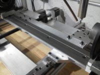
The next step was to mount the bottom support between the two bearings (without the leadscrew) and move the assembly up and down the rails to make sure I had a nice smooth movement. That was followed by tieing the rail assembly to the ends and manually measuring to get them parallel to the dovetail support. I always knew there would a followup truing of the entire assembly.

But the bowing or bellying out of the middle caught me by surprise. I expected the ends to be out of true, but in a linear fashion.

However, you guys have confirmed my worst fear, that my rails are not straight. I kind thought that would show up when I mounted the two bearings together and tested the movement up and down the length of the rails for a smooth ride, as it were. I couldn't detect any play in the bearings on the rails, but it must be there.

I do have a known straight bar, I will mount it between centers and figure out some way to mount a dial indicator on the router mount and see what I am up against. I know that seems elementary at this point, but I just couldn't imagine that my supported rails were anything near being this far out of true. But apparently, it is not an uncommon situation.

Again thanks to all for your experience, suggestions, and help. I will follow up when I get it figured out.

Gary
 
Thanks to all for the help and suggestions.

To answer some of your questions:

The rails came to me already mounted on the supports. I got them from a guy on eBay who said he got them from Glacern.com but that he had never used them. They appeared to be new when I got them. I knew from my previous experience that the rails (20mm) are pretty stiff to begin with, but yes, in an unsupported setup, they will flex. So when I got the supported rails, I pushed and pulled on them a little bit, but I just couldn't detect any give. I made the assumption that they must be straight (I know ASS U ME :wink:) Then I mounted them to the 8020, which is generally pretty straight stuff, and there wasn't any stress or force. The rail supports sat flat and flush on the 8020.
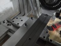
The next step was to mount the bottom support between the two bearings (without the leadscrew) and move the assembly up and down the rails to make sure I had a nice smooth movement. That was followed by tieing the rail assembly to the ends and manually measuring to get them parallel to the dovetail support. I always knew there would a followup truing of the entire assembly.

But the bowing or bellying out of the middle caught me by surprise. I expected the ends to be out of true, but in a linear fashion.

However, you guys have confirmed my worst fear, that my rails are not straight. I kind thought that would show up when I mounted the two bearings together and tested the movement up and down the length of the rails for a smooth ride, as it were. I couldn't detect any play in the bearings on the rails, but it must be there.

I do have a known straight bar, I will mount it between centers and figure out some way to mount a dial indicator on the router mount and see what I am up against. I know that seems elementary at this point, but I just couldn't imagine that my supported rails were anything near being this far out of true. But apparently, it is not an uncommon situation.

Again thanks to all for your experience, suggestions, and help. I will follow up when I get it figured out.

Gary

Oh Gary, the fun is about to start. Yes those rails will move. You can't rely on their stiffness to keep them straight. The last go around I actually milled channels for the linear rails that I used. That worked pretty good. It kept my 12" rails very straight. I gave up on 36" to 40" rails as this is a pain in the you know what. I use linear actuators now for the long travel. See the issue will be the sideways force your fasteners will have when you lock the rails down. It is amazing how much force this is. When you get an indicator on your machine loosen these screws up and then retitan them while watching the indicator.

Jim.
 
[...]

I do have a known straight bar, I will mount it between centers and figure out some way to mount a dial indicator on the router mount and see what I am up against. [...]
Gary

Save yourself some time and forget about mounting the straight bar perfectly "between centers" - you're not worried about being parallel to the centerline, you're worried about the bellied cut.

You could spend an hour trying to mount a straight bar between centers, and then you've still got sag in the middle to account for; trying to brace up that sagging middle WITHOUT influencing it to one side or the other will be a trick all its own.

Just lay your straight bar on the lathe bed and secure it with a couple of clamps so it's sort of parallel to your guide rails - a tape measure is accurate enough for this layout. Now mount your indicator and run up and down the full length. If your rails are not bowed, you should be indicating a straight line. Since it will almost certainly be a "taper" it may take you all of three seconds with a calculator to math out the ratio between the close end and the far end, and then determine if center point is consistent with a true taper.

TW
 
I just upgraded my home grown CNC X bed with a few improvements. I understand that my system is quite different than yours but there are a few lessons here that may be helpful.

My original machine plates were made from 6061 aluminum bar stock. Not flat enough. All my new plates are Mic-6 grade aluminum which is extremely flat.

My X plate was only 2” wide. I could not align my Y without removing my dovetail. What a guessing game. My X plate is now 4” wide. All adjustment bolts are now accessible. I have two slotted adjustment bolts on the top surface and one slotted adjustment bolt centered under the dovetail on the bottom surface. That gives me a center pivot bolt at each end to align with. With my X plate being 4” wide my Y carriage nut mounting to the X plate are also accessible in the center.

Flat plates = flat rails (& dovetail). Accessible mounting = easier alignment.
 

Attachments

  • IMG_20120128_182112.jpg
    IMG_20120128_182112.jpg
    45.2 KB · Views: 463
  • IMG_20120128_181905.jpg
    IMG_20120128_181905.jpg
    38 KB · Views: 478
Dan,

Thanks!! I always enjoy seeing other guy's setups. I went to your website and saw more of your inlay machine.

Tips/advice well-taken.

Gary
 
I just upgraded my home grown CNC X bed with a few improvements. I understand that my system is quite different than yours but there are a few lessons here that may be helpful.

My original machine plates were made from 6061 aluminum bar stock. Not flat enough. All my new plates are Mic-6 grade aluminum which is extremely flat.

My X plate was only 2” wide. I could not align my Y without removing my dovetail. What a guessing game. My X plate is now 4” wide. All adjustment bolts are now accessible. I have two slotted adjustment bolts on the top surface and one slotted adjustment bolt centered under the dovetail on the bottom surface. That gives me a center pivot bolt at each end to align with. With my X plate being 4” wide my Y carriage nut mounting to the X plate are also accessible in the center.

Flat plates = flat rails (& dovetail). Accessible mounting = easier alignment.

Starting off with good materials is the best option.Alot of materials have stresses in them, so getting 1 side milled flat is not going to work.It will just bow like a banana .
If you can not make it right, design it to be adjustable and then it can be made right.
From what I have seen with rails, the round bar on Ali blocks is not really that ideal for longer lengths.The linear flat rails are alot better made and are straighter as well as smoother running.But cost alot though.
Making a really good base/frame that allows you to level and true up the axis can not be underestimated.
 
Back
Top