You are using an out of date browser. It may not display this or other websites correctly.
You should upgrade or use an alternative browser.
You should upgrade or use an alternative browser.
Method for indexing the chuck on a full size lathe
- Thread starter Jr's Farm
- Start date
Obviously you want to be careful to not power the spindle when it's locked down, but for those of us without alot of big stationary tools, this helps make the ones we have multi-purpose.
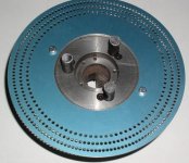
The outer row of 144 holes are spaced 2 1/2 degrees apart, the middle row of 120 holes are 3 degrees apart and the inner row of 90 holes are 4 degrees apart.
Also, to be clear, this particular indexing plate is mounted on my 6" 3-jaw. If you look closely you can still see all the degree numbers too. That was a bonus!
Attachments
Last edited:
Jr's Farm said:
Obviously you want to be careful to not power the spindle when it's locked down, but for those of us without alot of big stationary tools, this helps make the ones we have multi-purpose.
That looks very good. The way I did it when I was using my lathe for making pointed forearms and deco rings was to bolt a plate below my rear chuck. When I needed indexing I would clamp a indexer onto the table and lock it's nose in the rear chuck. This is one of the benefits of using full size equipment. You can make other needed items besides just cues.
Dick
Last edited:
I found this on ebay and modified it to fit my configuration.
http://cgi.ebay.com/ws/eBayISAPI.dll?ViewItem&ssPageName=STRK:MEWAX:IT&item=360119585721
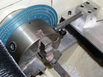
Dialed it in and bolted it snug. As long as I back out the indexing dog and lock it out or remove it, I'm good to go. The indexing plate stays in place, out of the way.
http://cgi.ebay.com/ws/eBayISAPI.dll?ViewItem&ssPageName=STRK:MEWAX:IT&item=360119585721
Dialed it in and bolted it snug. As long as I back out the indexing dog and lock it out or remove it, I'm good to go. The indexing plate stays in place, out of the way.
QMAKER said:Great idea. Thought of doing something like that myself and now I am motivated to carry it thru. What size was the bore on the indexing plate?
And, is that a Jet lathe you have it mounted to?
Jet GHB1340.
I'm trying to recall, but 4.6" +/- seems like the bore size. I sized it about an 1/8" larger than the actual nose plate.
I was going to drill and tap (3) holes in the back of my chuck to mount it to, until I noticed (2) pre-tapped holes already there. Seems to be okay with only (2).
That is very nice Frank.
I have a pedestal I mount to the ways, and a 5C indexer is mounted to that, set to the appropriate height. Each time that is setup, it has to be indicated in ofcourse, which makes your setup very nice.
Though it probably isn't a big deal, the only drawback of yours is you can't use the power feed when milling or cutting grooves. I can because my indexer is independent of the spindle.
Kelly
bunep
Registered
nice..
hi..
nice indexer..
do you place the indexer spike on tapering attachment?
can i see the pic of it?
h
hi..
nice indexer..
do you place the indexer spike on tapering attachment?
can i see the pic of it?
h
Jr's Farm said:
Obviously you want to be careful to not power the spindle when it's locked down, but for those of us without alot of big stationary tools, this helps make the ones we have multi-purpose.
The outer row of 144 holes are spaced 2 1/2 degrees apart, the middle row of 120 holes are 3 degrees apart and the inner row of 90 holes are 4 degrees apart.
Also, to be clear, this particular indexing plate is mounted on my 6" 3-jaw. If you look closely you can still see all the degree numbers too. That was a bonus!
Kelly_Guy said:Though it probably isn't a big deal, the only drawback of yours is you can't use the power feed when milling or cutting grooves. I can because my indexer is independent of the spindle.
Kelly
Yep. That is one of the drawbacks. I haven't done enough research or digging around yet to see if it's even possible, but feeding manually isn't as bad as I suspected.
bunep said:hi..
nice indexer..
do you place the indexer spike on tapering attachment?
can i see the pic of it?
h
I posted a handful of pics in this thread, starting at post #16:
http://forums.azbilliards.com/showthread.php?p=1567453#post1567453
I meant to start my own thread at the time but that one popped up at the same moment and it seemed relevant. Maybe someday I'll post some more pics and a write up on it too.
Hope that helps
")
Regards,
Frank
Jr's Farm said:Yep. That is one of the drawbacks. I haven't done enough research or digging around yet to see if it's even possible, but feeding manually isn't as bad as I suspected.
What about a gear motor with a toggle & belt going to Your feed handle? Might be able to make something up to feed the carriage that way, if there's a way to mount a bracket for It that bolts on and off easily.
I haven't looked at the gearing in the transmission yet, but it might be as simple as removing an idler gear somewhere. If I can do that and the power is on the wrong side of the gearing, then another motor might be the answer.
If I ever find the answer I'll let you guys know.
If I ever find the answer I'll let you guys know.
On most of the cheaper chinese lathes, there is a belt cover on the left side of the headstock. If you remove that, you will see that there are a series of gears connecting the spindle to the feed transmission. This is also where the change gears go on the lathe to change from inch to metric feed. You could remove these gears and then add a motor to the where convenient. This should work with the lathes that have the thread gearbox where you pull a pin out and slide a lever back and forth to select another gear ratio.
On your more expensive jet lathe, that has the rotating knobs for the gear ratio adjustment, the gears that link the spindle to the feed transmission might be inside the headstock. So it would probably take a lot more modifications of the machine to make this happen, if that is true.
On your more expensive jet lathe, that has the rotating knobs for the gear ratio adjustment, the gears that link the spindle to the feed transmission might be inside the headstock. So it would probably take a lot more modifications of the machine to make this happen, if that is true.
Taking out the change gear was where I was going to start. In my head it would seem to me that the spindle would still be under power and the carriage feed would not. So then a pully and seperate motor would be necessary to drive the disconnected feed screw.
If that is the case I'm not sure how important that modification will be to me. Might be simpler to put a pulley and motor on the hand crank itself as Cue Crazy suggests. (Hmmmm)
On second thought, (or is it third/fourth by now) it would be nice to drive it at the lead screw so I could use the half nut for engaging/dissengaging the travel, as killing and braking a seperate motor might not be as accurate or handy.
Last edited:
I added this one to my Cue Smith Delux . 72 on out side and 40 on inside. Along with the 24 the cueSmith comes with.

Jr's Farm said:Taking out the change gear was where I was going to start. In my head it would seem to me that the spindle would still be under power and the carriage feed would not. So then a pully and seperate motor would be necessary to drive the disconnected feed screw.
If that is the case I'm not sure how important that modification will be to me. Might be simpler to put a pulley and motor on the hand crank itself as Cue Crazy suggests. (Hmmmm)
On second thought, (or is it third/fourth by now) it would be nice to drive it at the lead screw so I could use the half nut for engaging/dissengaging the travel, as killing and braking a seperate motor might not be as accurate or handy.
On most of the Chinese lathes I've seen there is a spring loaded pin on the front bull gear which needs to be pulled free to run the back gear. All that needs to be done is to release this pin and not engage the back gear and the gear train will work as usual but the front of the spindle with the chuck attached will be free.
Dick
Obviously you want to be careful to not power the spindle when it's locked down, but for those of us without alot of big stationary tools, this helps make the ones we have multi-purpose.
The outer row of 144 holes are spaced 2 1/2 degrees apart, the middle row of 120 holes are 3 degrees apart and the inner row of 90 holes are 4 degrees apart.
Also, to be clear, this particular indexing plate is mounted on my 6" 3-jaw. If you look closely you can still see all the degree numbers too. That was a bonus!
Very nice!!!
That looks very good. The way I did it when I was using my lathe for making pointed forearms and deco rings was to bolt a plate below my rear chuck. When I needed indexing I would clamp a indexer onto the table and lock it's nose in the rear chuck. This is one of the benefits of using full size equipment. You can make other needed items besides just cues.
Dick
Dick,
Do you have a photo of your old setup? I was looking into this and really like this idea. Would like to explore options before I begin.
I should have known better than to post ebay links, so here's a link to the indexing plate manufacturer's website.
"Alisam"
http://alisam.com/page/14g9e/Woodworking_turning_OT.html
Lot's of great stuff there. Hope this helps.
Regards,
Frank
"Alisam"
http://alisam.com/page/14g9e/Woodworking_turning_OT.html
Lot's of great stuff there. Hope this helps.
Regards,
Frank
Dick,
Do you have a photo of your old setup? I was looking into this and really like this idea. Would like to explore options before I begin.
I haven't done it this way in years so I just through it together for this picture. It does show the basic layout.
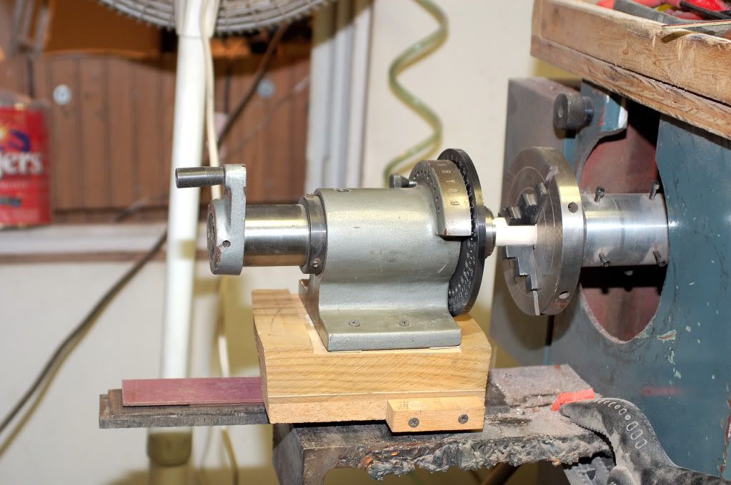
Dick