My CNC lathe design

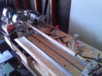
here's some additional photos...

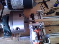
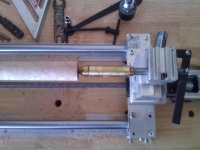
I got a dead center and a live center from Porper and I modified the live center to screw onto the taig tail stock.

I drilled it and threaded it in 3/8ths-24 and now it threads right onto the taig tail stock.

I'll have to get a concave live center and do the same thing.

Jaden

Also, these pictures give a more accurate portrayal of just how big these chucks are. That is the standard dead center for a Porper model B and that cue is just slightly oversized. Needs a couple of finishing passes after I put the ring work, joint collar and butt collar on it.
 

Attachments

  • WP_000018.jpg
    WP_000018.jpg
    52.6 KB · Views: 417
  • WP_000019.jpg
    WP_000019.jpg
    54.8 KB · Views: 433
  • WP_000020.jpg
    WP_000020.jpg
    50.6 KB · Views: 390
Actually I will be doing both...

That was close to my first thought which would actually be a hard stop. Limit switches are great for stopping and homing, but when it comes to running metal into spinning metal, go with a hard stop.

dld

I will be doing a hard stop and a limit switch on the hard stop. The limit switch will be good for using as an auto zeroing function. so I'm definitely going to use a limit switch, but you're right, a hard stop is better for making sure metal doesn't go to metal, because when (not if, unless you replace them all the time without reason to) they go bad, if you rely on them, you're going to have an expensive mess and if you're close to it when it does, you'll have a red mess TOO!!!!

Not a good thing. I have enough red messes as it is, often without even realizing it until I've bled all over the place...

Jaden
 
I will be doing a hard stop and a limit switch on the hard stop. The limit switch will be good for using as an auto zeroing function. so I'm definitely going to use a limit switch, but you're right, a hard stop is better for making sure metal doesn't go to metal, because when (not if, unless you replace them all the time without reason to) they go bad, if you rely on them, you're going to have an expensive mess and if you're close to it when it does, you'll have a red mess TOO!!!!

Not a good thing. I have enough red messes as it is, often without even realizing it until I've bled all over the place...

Jaden

Jaden

I'd recommend using separate switches for home and limit. You can use a switch as dual function, but I find that they work better if you use different switches for the different functions. Limit switches can be simple lever operated switches, but for homing, you need something much more accurate, like an optical switch. Limit switches need a little "run through" so the machine has some room to stop once the switch is tripped. Optical switches should be located to provide a useful "machine home" position to work from. I personally don't use any limit switches. The primary reason is that I only have interference when both x and y are in a certain place at the same time. In other words, each axis normally goes to that location in normal operation as part of the programs I run. But, if they both are there at the same time it's a problem. Limit switches can't tell if both are there at the same time, so they would trip and stop my machine when it's running normal programming. Yes, I've crashed a few machines, but most everyone who seriously uses CNC has crashed machines. Including $250,000 commercial machines. We've learned to test out programs when changes are made, and double check key entries and numbers as we enter them.
 
cnc Lethe

As Royce said, homing is tricky. Opticals would be your best bet, but make sure you can keep dust and dirt out of them. Only thing that jumps out at me, is the lead screw under the cutting area, I'd look into some kind of cover, dust and chips will eat those delrin nuts. With the big head stocks you should be able to do some neat stuff. Live threading, joint work, all kinds of real cnc lathe things. And oh by the way, limit switches are for girls, real men crash their machines. It's a right of passage.:grin:
 
here's the new base mount for the spindle

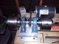
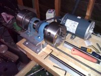
Here's a couple of pics of the new base mount for the spindle and drive.

Also you can see the indexing holes I had drilled into the back plate in one of the pics.

I'll be making a mount with a screw to lock into the indexing positions for various tasks that require indexing.

Jaden

p.s. the hard stops are the next thing I'm adding.
 

Attachments

  • WP_000021.jpg
    WP_000021.jpg
    51.4 KB · Views: 276
  • WP_000022.jpg
    WP_000022.jpg
    64.5 KB · Views: 273
Back
Top