You are using an out of date browser. It may not display this or other websites correctly.
You should upgrade or use an alternative browser.
You should upgrade or use an alternative browser.
Solid Model
- Thread starter PolarBear
- Start date
JoeyDenton
Registered
Looks right to me. What software is that?
JoeyDenton
Registered
Nice. I got to play with solidworks when I was taking my MasterCAM certification tests. Very cool software.
I was just playing around with solidworks and full splicing as you were posting this..
heres what i got:
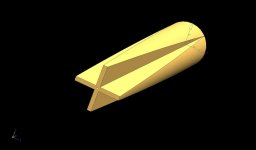
Forearm with V-Grooves cut inside for mating with the points

Points with V-Grooves cut inside for mating with handle short points

Handle with second splice, Davis Style.

All together in a square, before turning

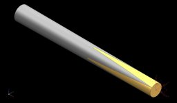
Cyclindrical cue, untapered

heres what i got:
Forearm with V-Grooves cut inside for mating with the points

Points with V-Grooves cut inside for mating with handle short points

Handle with second splice, Davis Style.

All together in a square, before turning

Cyclindrical cue, untapered

Wayne-Holmes
Professional Retiree
Looks good in theory. A drawing is approximately 5% of the project. The killer part is the other 95%...Making the drawing work.
An old saying comes to mind; "You can draw a monkey, but can you build one?"
An old saying comes to mind; "You can draw a monkey, but can you build one?"
Looks good in theory. A drawing is approximately 5% of the project. The killer part is the other 95%...Making the drawing work.
An old saying comes to mind; "You can draw a monkey, but can you build one?"
You mean you can't make molds out of those drawings ?
Props to the drawers.
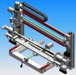
I once drew this to figure out something I was interested in.
Last edited:
JoeyDenton
Registered
How long have you been doing CAD/CAM? Mastercam "X" series or older?
I've been using MasterCAM since MasterCAM 8. I actually just upgraded from x4 to x5 over the last month or so. I've also used a variety of CAD/CAM softwares over the last 10 years, but it's hard to beat what x4-x5 can do.
Looks good in theory. A drawing is approximately 5% of the project. The killer part is the other 95%...Making the drawing work.
An old saying comes to mind; "You can draw a monkey, but can you build one?"
Funny...I know I've heard this old saying before. I believe it was my grandfather who used to design fiberglass boats. You may have heard of his old company...Glasply. All his designs were stored in his head. Rarely did he draw things out or use blueprints (back in those days CAD wasn't even a daydream).
Here are some updates I made to my full splice to try to add veneers to full splicing like in Davis' Blanks.
Making the full spliced veneers together was not as easy as I had thought. After some analysis, i figured out how to cut and piece each point veneer stack together, that way the points come out sharp on both ends.


Veneer Stacks in between the forearm and points

Veneer in cue


Sharp points on both ends!!
After trying to model this, I can see why a few makers attempt to make full splice double sharp ended cues.
Making the full spliced veneers together was not as easy as I had thought. After some analysis, i figured out how to cut and piece each point veneer stack together, that way the points come out sharp on both ends.


Veneer Stacks in between the forearm and points

Veneer in cue


Sharp points on both ends!!
After trying to model this, I can see why a few makers attempt to make full splice double sharp ended cues.
Last edited:
Wayne-Holmes
Professional Retiree
Your Grandfather was a talented man!! Yes I'm familiar with Glasply Boats.Funny...I know I've heard this old saying before. I believe it was my grandfather who used to design fiberglass boats. You may have heard of his old company...Glasply.
Wayne-Holmes
Professional Retiree
Many Designers are at a disadvantage in that they don't have the benefit of actually having used the manufacturing tools (cutting tools in the case of cues) and have little to no idea what the tool can or cannot do.What amazes me , is how even with solid modeling of components, designers can still design things that can not be made, or in some cases,the components can not be assembled once made.
No reflection on the posters showing their drawings as they're actually very good. However, that same old saying still applies.
Any drawing, whether done by computer or hand, is generally considered to be "conceptual". In practical application dimensions and angles can and often do change.
When a drawing is carried forward to the manufacturing process, that's when one will realize the meaning of "can you build a monkey".
Last edited:
Here are some updates I made to my full splice to try to add veneers to full splicing like in Davis' Blanks.
Making the full spliced veneers together was not as easy as I had thought. After some analysis, i figured out how to cut and piece each point veneer stack together, that way the points come out sharp on both ends.


Veneer Stacks in between the forearm and points

Veneer in cue


Sharp points on both ends!!
After trying to model this, I can see why a few makers attempt to make full splice double sharp ended cues.
once this cue is tapered the points will be about half as long. Your angle on top is way to extreme.
Many Designers are at a disadvantage in that they don't have the benefit of actually having used the manufacturing tools (cutting tools in the case of cues) and have little to no idea what the tool can or cannot do.
No reflection on the posters showing their drawings as they're actually very good. However, that same old saying still applies.
Any drawing, whether done by computer or hand, is generally considered to be "conceptual". In practical application dimensions and angles can and often do change.
When a drawing is carried forward to the manufacturing process, that's when one will realize the meaning of "can you build a monkey".
Wayne, not until after I talked to you about some of my initial conceptual drawings did I start to grasp what you are saying here. Recall my question in one of our conversations about doing 6 windows in the butt sleeve? You make a great point here.
Wayne-Holmes
Professional Retiree
Yep, I remember. That's why I only put one HUGE window in your 4 point cueWayne, not until after I talked to you about some of my initial conceptual drawings did I start to grasp what you are saying here. Recall my question in one of our conversations about doing 6 windows in the butt sleeve? You make a great point here.


