Jr's Farm said:
"...my next step is coming up with a good way to index the headstock. Anyone with pics of that on a full size metal lathe?.."
Regards,
Frank
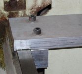
Frank-thanks for the detailed pics!
How did you mount the small alluminum pieces to the back of the lathe? Did you screw into the groundways?
-------------------------------------------------------------------
In regards to your indexing question. (try to picture this
")
I have a large 13.5 x 40 Grizzly. Way back when I was able to obtain a large indexing pully much like the one from Taig Tools or Chirs Hightowers lathe. The back of my spindle has a straight od AFTER the od threaded part.
I measured several times to get the od of my spindle and had a shop bore the id of the large indexer pully.
Now, this lathe has (2) double threaded pins that hold the fiberglass pully cover on. The upper pin is double threaded (as well as the lower pin) and both pins have a hexagon body between the (2) threaded ends. I cut off the outer threaded part and drilled the flat top part of the hex to hold the rectangular "indexing pin bar" onto it. (the rectangular indexing pin bar has a threaded hole to hold the threaded "indexer pin" in place.) It overhangs into space (half on the hex pin and half into space) and lines up perfectly with the pully. LUCKY!!!! (actually, you can slide the indexer pully along the straight od of the lathe spindle.)
I put a little ice in the spindle and the indexer slid on like butter! Lined it up under the pin and locked it into place via (2) set screws threaded into the lathe spindle. Once you take the ice out, it LOCKS the indexer as well!
I might mention that it is best you use a tapered point indexer pin to hold the indexer into position when indexing. You get a much better seat into the indexer holes this way.
They only draw back is the inability to place the fiberglass lathe cover back on AND working a foot and a half away from the front of the spindle when indexing. I have yet to bore a larger odd shaped hole in the cover to slide it back on. I don't think it would be very funcional as it would have to be duct taped after put into position to cover the elongated hole.
Now comes the real problem...
Only AFTER did I decide to put on a 3-jaw chuck/adapter on this end. Had to pull everything off and back to the machine shop for an even larger id on the indexing pully.
Works great less the absence of the glass cover:wink:
No pics. I am at "my other job" right now...
")