Another inlay pocket problem

DanO

AzB Silver Member
Silver Member
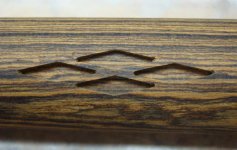
Any Ideas on the cause? I’m cutting clockwise around the pocket on my clean up pass, removing .003” material wall x .14” deep. Entry point and exit is @ 12 o’clock. Ø.031 cutter, Ø.030 in my program, .015” radius in the pocket. Cut fine in pine. Not so fine in bacote.

I’ll probably start with increasing my radius size.

Thanks in advance.
 

Attachments

  • DSC04030.JPG
    DSC04030.JPG
    64.5 KB · Views: 862
  • DSC04028.JPG
    DSC04028.JPG
    94.6 KB · Views: 869
That would make more sense since I didn't see the problem in my test pieces or the four diamonds I put in the forearm. I had my pin chucked in a 5c collet. My butt was pushed into a V point. I may not have had it tight enough and was getting a slight movement. I have a 5c on both end. Next time I'll use it. I'll try the same program in some scrap bacote but make sure it is clamped.
 
Hi Dano,

CNC Gremlins would be my guess.

No seriously, I am sure some of the CNC brains will come to the rescue here.

Good Luck,

Rick
 
I do My inlay manually so have no idea If It's software related or not, and I don't have the cnc experience to even make a good guess, but Looking at It makes Me wonder if It could be backlash or play related? It's obvious to me that east to west is the worse part, but in the second picture It looks like there was a hair of It in the north to south direction on the first pass, but like It got better the deeper the cut went. Possible that part was just related to the end mill flexing, before getting deeper into the cut where It had more support from the sidewalls to stay in the pocket. Guess that would depend on the size of the mill. Possible it's just that the pocket is not blown out as well on the tips, or Maybe It's just an illusion that I'm seeing though.
I'm sure someone that has experienced the same thing will know what the issue is just from seeing the pictures.

Greg
 
I honestly think my cue must have been loose. My machine is running extremely smooth since I took everyones advise and reduced my acceleration. When I made my clean up pass, the cutter really groaned in the problem areas. So if it wasn't my moving then it "sounded" like it happened then. I'm really ticked this happen on a cue. I made 3 test cuts in a piece of pine playing with the fit and it did not happen then.
 
I honestly think my cue must have been loose. My machine is running extremely smooth since I took everyones advise and reduced my acceleration. When I made my clean up pass, the cutter really groaned in the problem areas. So if it wasn't my moving then it "sounded" like it happened then. I'm really ticked this happen on a cue. I made 3 test cuts in a piece of pine playing with the fit and it did not happen then.


It well could be if you suspect that, I've had very similar results with My manual machine, and It turned out that something was loose. Sometimes I forget to lock My milling table back down before cutting males out, and something like that happens. If you try It again on some scrap like you mentioned maybe that will help confirm one way or the other.
 
Last edited:
Looks to me like the Cutter Comp is messing you up when it switches directions on the X axis.

If you're not using CC then make sure there is no dwell set at the ends.
I would also consider Climb Milling the Finish pass. Converntional milling (cutter and tool path both going clockwise) tends to dig in. Climb milling generally gives a smoother finish. Might want to slow down your feedrate as well. I would actually slow it way down when it get to that point and see if it moves in to cuts those 2 spots... from what I see it doesn't look like a smooth transition out of that corner.
 
When in a finish path, we never start or end in a corner. I always start well inside the area to be worked on. In the 1st XY move is when cutter comp if applied is put on, but before the cutter is near the wall or side being cut. Then goto the start of the radius, make the profile and then come away from the wall/side . After it is clear then the comp can be taken off in an xy move.
If the Z axis is not perfect, there can be a dwel or divot mark as the cutter is retracted.
It does not look like mechanical XY problems as the other end of the profile is looking normal.
 
I'm cutting both my rough and finish passes CW. In Bobcad V23, where do I change my finish pass to go CCW? Can't find it for the life of me. Or do I have to post two different codes then cut and paste outside of Babcad?
 
Snip... I would also consider Climb Milling the Finish pass. Converntional milling (cutter and tool path both going clockwise) tends to dig in. Snip...

At the risk of getting off topic, I agree that conventional milling tends to deflect inward, or "dig in" when cutting parts and outward when cutting pockets. For that reason, conventional milling a finish pass CAN result in smaller parts, and larger pockets than expected. However, the deflection can be managed for higher accuracy.

I climb cut when roughing hardwoods, which due to tool deflection, produces larger parts and smaller pockets, leaving an amount of material for a finish pass equal to 1/8th of the mill diameter. Leaving that amount for your finish pass, the cutting resistance of the wood is approximately balanced by the tendency of the bit to drift into part, resulting in minimal bit deflection. I then conventional cut the finish passes on both, resulting in an accurately sized part or pocket.

Just my own .02.
 
I'm cutting both my rough and finish passes CW. In Bobcad V23, where do I change my finish pass to go CCW? Can't find it for the life of me. Or do I have to post two different codes then cut and paste outside of Babcad?

The direction of cut is determined when creating a contour in BobCad. There are two buttons: [CW] and [CCW] You can also change the direction of your already created contour, but I can't remember how to do that off the top of my head, but there is a "reverse contour" function somewhere. Added: Utilities > Reverse Contour.
 
Last edited:
I understand the contour function and changing the direction before creating the contour. My problem is trying to change the contour direction just for the clean up pass. Maybe reverse contour is what I'm after? I'll do some more research on the subject.
 
I understand the contour function and changing the direction before creating the contour. My problem is trying to change the contour direction just for the clean up pass. Maybe reverse contour is what I'm after? I'll do some more research on the subject.

It's not a built in feature in BobCad, v23 anyway, and will not solve the problem that you posted about in this thread. You have to use a separate feature(profile/pocket) and a separate layer in your CAD with a different contour on each layer to pull it off. If you're not having a problem with your overall inlay fit, I wouldn't bother changing what is working for you, but if you are, this may make things right for you.

I have had BobCad insert "surprises" like you posted here into my toolpaths on many occasions, so I always test before cutting into a cue. When BobCad decides to insert these surprises into the G-code, I usually make a change in the CAM to change things up and re-post the new code and test again. In my experience, BobCad 23 has some bugs.
 
I always drill the corners of the pockets prior to milling . This will leave less for the small endmills to remove (.025 dia circuit board drill) . I also would never start in a corner always on a larger radius or flat area with a lead in and I have found the climb milling works much better than conv milling . Do you step down in endmill sizes?

Carlton
 
Last edited:
It's not a built in feature in BobCad, v23 anyway, and will not solve the problem that you posted about in this thread. You have to use a separate feature(profile/pocket) and a separate layer in your CAD with a different contour on each layer to pull it off. If you're not having a problem with your overall inlay fit, I wouldn't bother changing what is working for you, but if you are, this may make things right for you.

I have had BobCad insert "surprises" like you posted here into my toolpaths on many occasions, so I always test before cutting into a cue. When BobCad decides to insert these surprises into the G-code, I usually make a change in the CAM to change things up and re-post the new code and test again. In my experience, BobCad 23 has some bugs.

i'm wondering if v24 is different? "currently using 24" It will allow me to pocket and profile off the same geometry, and in the same routine. I dont have to create seperate layers. Not sure if its really right or wrong to do it that way but i just kinda taught myself, mostly because it allows me to do more than 2 tool changes.

If i was doing the diamonds as shown above, i would have drawn them without any radius "not saying theres anything wrong with radius" Hog with 30, cleanup with 15, then profile with 10 all in the same program, and all from the same geometry. Is this relevant to what your explaining above or am i way out in left field?
 
Last edited:
It sounds like you may be on to something with not having everything truly locked down solid,but I have something that might help.

When you start the pocket,are you going to full depth right off the bat?

Are you "ramping" in where you take say a .025 deep cut,then the cutter automatically drops down (in a progressively downward angle,and slowly so the cutter doesn't load up and break) another .025 without changing direction,and so on?

What it LOOKS like,is maybe a software setting where the cutter is actually doing a "helix" where it takes a circular path to plunge to the depth for your cut,then goes elsewhere.

I've seen GOOD machinists/T+Diemakers make a wrench or some other part out of a flat plate or block,and the cutter takes the full path to make the outline of a part,then moves to a place outside of the desired shape,plunges before the next cut,then moves on.

In doing the CNC work I did in school,I made parts for the class shop,my required projects,and even stuff I made for Auto/Industrial Maintenance class shop.

Instead of making a HSS endmill plunge into steel to get to proper depth,I always drilled a hole,set that as X0,Y0,and set it so when the program started,the end mill would drop to depth or say Z-.025,take a cut,then when it dropped for the next step,it did so in that hole,then came out.

Hopefully,this will shed some light on what may be causing your problem,and ask then when you DO find your solution,you post it here,so it might help others,and keep things moving the way they should be,helping each other. Tommy D.
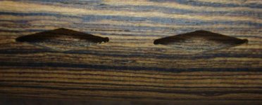
 
It looks like there was some movement in the cue while cutting. I used to get a similar cut when I was having an issue with my vaccum table not holding the flat stock down solid. You can put a dial indicator on the side of the cue and rerun the program and watch for movement in the cue sideways. If that is ok, I would look for play in the Z axis or the spindle itself.
 
another

You never told us what cnc machine you are using. That would help, if it
is not a well known type, the construction of it would be helpfull, along with
mechanical items, like ball screw type and controller settings. it's probably
the cue moving, but that's a lot of movement with a small cutter. The part about slowing down
the acceleration is what interests me. Was it machine rigidity or backlash problems that
led to slowing things down.
 
Dan,

Could your Y have crashed slightly and you lost steps. That happened to me because I moved my fixture to test a v groove program I wrote. When I slid the fixture back I lined up to the wrong mark.

Rick
 
Back
Top