Cutting points with a milling machine

Busbee Cue

AzB Silver Member
Silver Member
Hello,

I have spent a few hours using the search function and reading all I could find on this topic.

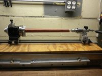
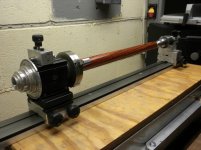
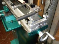
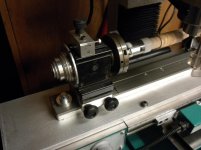
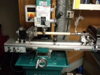
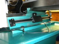
The setup would be a small taig headstock with indexer and a drilling tail stock attached to a piece of dovetail mounted on a 1/2" thick by 2" wide piece of aluminum.

What would be the best way to attach this to a milling table, a vise with swivel or attach it to the table without a vise and have it swivel on one end and a lock down setup on the other end?

Any advice will be greatly appreciated.
 

Attachments

  • DSCN1129.jpg
    DSCN1129.jpg
    95.7 KB · Views: 1,116
  • DSCN1130.jpg
    DSCN1130.jpg
    93.6 KB · Views: 1,121
I supposed this picture could be for general illustration purposes and not the final setup, but:
Maybe it's just the camera effect, but it looks like the butt end is in the chuck and the shaft end is in the tailstock. If so, how are you going to get a cutter to cut all the way into the butt end for the base of the points?
As for your mounting question, I have no suggestion there.
My 2 cents,
Gary
 
One easy way is to mount your rig on a wider, longer piece of at least 1/2" aluminum plate then properly offset the wide plate,very accurately drill, countersink, and tap bolt holes using tapered head allen head bolts, through the aluminum into the mill table with a curved slot at the end of the table where the offsetting will take place. You now have a setup you can take on and off and replace accurately by measuring a marked point on the table to the marked point on the wide plate with a set of calipers. For example, 2.045" for 4 pointers, 1.938"for 5 pointers and 1.625" for 6 pointers. Write these down and calibrate your calipers.
 
I supposed this picture could be for general illustration purposes and not the final setup, but:
Maybe it's just the camera effect, but it looks like the butt end is in the chuck and the shaft end is in the tailstock. If so, how are you going to get a cutter to cut all the way into the butt end for the base of the points?
As for your mounting question, I have no suggestion there.
My 2 cents,
Gary

There needs to be a sacrificial end on the butt end of the forearm or core it and leave the dowel sticking out.....

Kim
 
Here are some pictures of my set-up.


here is a picture of the bottom:


You will notice that I have a pivot point that fits into the slots on the mills table that enables the jig to pivot but hold it's position on this end of the jig.

At the other end of the jig I offset a predetermind amout so as to give the points the length and depth that I desire.


Once I have the jig in the proper place for the length and depth I use table clamps to lock down and hold in place. You can see their placement in the first picture.

I use a 2.5" diameter V shaper head to do the actual cutting. Works very well. I have a CNC Gantry system which I could be doing this operation on but as easy as it is to use I just have never got around to changing over.


Dick
 
One easy way is to mount your rig on a wider, longer piece of at least 1/2" aluminum plate then properly offset the wide plate,very accurately drill, countersink, and tap bolt holes using tapered head allen head bolts, through the aluminum into the mill table with a curved slot at the end of the table where the offsetting will take place. You now have a setup you can take on and off and replace accurately by measuring a marked point on the table to the marked point on the wide plate with a set of calipers. For example, 2.045" for 4 pointers, 1.938"for 5 pointers and 1.625" for 6 pointers. Write these down and calibrate your calipers.

I agree with everything here except the locating with (tapered) flat head screws part. The location will only be as good as the threads you've tapped, and there is usually .005"-.010" tolerance on thread taps. The screws have pretty big tolerances also (taper to thread). locating pull dowels are the only way to have repeatable locating of this jig. You could also use precision ground shoulder bolts, but that is basically the same as the pull dowel method. More work though, but the the shoulder would have to be for example, 1/2" shoulder 1" long with 3/4" long 3/8-16 thread. Indicate your jig in, tie it down with clamps, drill with tap drill 2+ inches, then drill and ream your 1/2" holes 1.250" deep, then go back and tap the holes. Location and tied down. Personally I like the pull dowel method. Indicate the jig, tie it down, pop two drilled and reamed holes for dowels, use your T slot clamps to keep it tied down, and done. Less holes in your mill table. If you have to have more than one angle set up. Then you have one constant dowel at one end that the jig rotates on and multiple holes at the other end, one for each angle (mark them so you know what angles are what) I hope I explained this well, It would be easier to draw it out. If you would like some help or info PM me and we'll exchange numbers and talk.
Tom

Very good information Tom.
 
If I were you, I would swap out the live center for a dead center about 1/2 inch in diameter with a 60 degree point. You can make one or buy one from ebay or various parts catalogs. That way, you will have plenty of room for the cutter to get out of the way. Im sure you could still do it with the live center, but I have learned (the hard way in most cases) that its far better to have a little extra room, instead of not enough. Lol.

Joe
 
Hello,

I have been messing around with this jig setup and have it attached to the milling table with 6 t-nuts with the tailstock and indexer on a rail with a pivot on one end and a lock down on the other end. The fixture is very easy to remove and replace with repeatable placement.

Once I get my offsets figured out for the number of points I want to cut I was thinking about putting a center mark on the bed and mark each offset for each number of points on the lock down bar in the first picture.


Is the pivot point on the end better than having it further up on the bed or would it not make any difference? If anyone has any suggestions on any improvements they will be appreciated.
 

Attachments

  • DSCN1157.jpg
    DSCN1157.jpg
    88.6 KB · Views: 579
  • DSCN1158.jpg
    DSCN1158.jpg
    85.4 KB · Views: 587
  • DSCN1159.jpg
    DSCN1159.jpg
    87.9 KB · Views: 560
  • DSCN1160.jpg
    DSCN1160.jpg
    89.3 KB · Views: 664
Last edited:
Hello Bill,

I like it pretty good. If the cutter rotation was a bit faster it would be a lot better but if I take smaller passes it works just fine.

I added a cheap Dro to the Y axis so dialing in on multiple passes is a lot easier. The Dro was around $24 from Grizzly, it was fairly easy to mount and so far it seems to work very well, you can't expect to much for this price but it seems to do the job.

Here are a few pictures of the Dro and a forearm I made messing around with the setup.
 

Attachments

  • DSCN1186.jpg
    DSCN1186.jpg
    91.3 KB · Views: 229
  • DSCN1187.jpg
    DSCN1187.jpg
    91.4 KB · Views: 226
  • DSCN1188.jpg
    DSCN1188.jpg
    93.7 KB · Views: 233
  • DSCN1146.jpg
    DSCN1146.jpg
    101.4 KB · Views: 227
Back
Top