Lets design a machine to test CTE

iusedtoberich

AzB Silver Member
Silver Member
Screen Shot 2015-10-08 at 11.30.12 PM.jpg


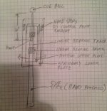
What if we designed a cue-robot like machine...

1. That had a fixed pivot point length from the CB of lets say 10" (common bridge point)
2. Had a linear bearing that the cue rode on in during its entire travel (ensuring a perfectly straight stroke)
3. It was two plates. A base plate that is stationary relative to the slate, and the top plate, that would pivot with respect to the stationary plate. All of the cue carrying components, such as at the linear bearing, would be attached to the top plate, and move with the top plate.
4. The bottom plate would have hard stops, to limit how many degrees the top plate (and thus the cue) could pivot. The hard stops could be calibrated for exactly 1/2 tip of rotation (for the mounted cue).
5. The cue could be hand powered, and the linear bearing would guide it.

To use it, one would start with the top plate against one of the pivot hard stops. Then, they'd eyeball the alignment of the stick with the CTE points on the CB/OB. They would do this alignment by moving the entire lower plate assembly. They would follow the CTE instruction for the given shot, as to what to align with what.

Once the alignment was set, the user would pivot the top plate until it hits the hard pivot stop in the other direction, which would again be 1/2 tip. (or full tip, whatever the CTE instruction is for the test shot).

Then the user would stroke the cue.

This could be tried for small variations in shot angle, that were still within the same instruction set of CTE. (It would be harder to make the jig fully adjustable to allow all shot ranges). Thus, it could be designed to only follow the instruction set for the 15 deg perception shots, for example.

What do you think? Could this prove or disprove if CTE is a system that follows an explicit set of instructions?
 
Last edited:
Screen Shot 2015-10-08 at 11.25.03 PM.jpg

Screen Shot 2015-10-08 at 11.25.17 PM.jpg


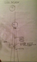
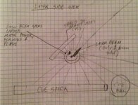
A rotating laser that will make a straight line (like those used on construction circular saws mounted on the saw arbor), could be mounted above the stick. This laser line would make a laser "plane" that goes through the entire length of the stick (on its centerline), and then even further forward onto the CB and the cloth.
 
Last edited:
How will your robot test things like "acquiring the visual", "3D perception", "rotating edges" - and whatever other excuse for subconscious adjustment they come up with this week?

pj
chgo
 
Linear bearings are awful.

They are noisy, often sloppy, all those single points of contact make vibration and issue.
A fixture like you propose shouldn't incorporate linear bearings.
Doing so would make something that is a pleasure to use, into something miserable.

RMS
 
A laser and a cue can not share the same centerline.

A good example is that the bore of a rifle, and a telescopic sight, (a scope), can not share the same centerline.
 
Last edited:
View attachment 398624


What if we designed a cue-robot like machine...

1. That had a fixed pivot point length from the CB of lets say 10" (common bridge point)
2. Had a linear bearing that the cue rode on in during its entire travel (ensuring a perfectly straight stroke)
3. It was two plates. A base plate that is stationary relative to the slate, and the top plate, that would pivot with respect to the stationary plate. All of the cue carrying components, such as at the linear bearing, would be attached to the top plate, and move with the top plate.
4. The bottom plate would have hard stops, to limit how many degrees the top plate (and thus the cue) could pivot. The hard stops could be calibrated for exactly 1/2 tip of rotation (for the mounted cue).
5. The cue could be hand powered, and the linear bearing would guide it.

To use it, one start with the top plate against one of the pivot hard stops. Then, they'd eyeball the alignment of the stick with the CTE points on the CB/OB. The would do this alignment by moving the entire lower plate assembly. They would follow the CTE instruction for the given shot, as to what to align with what.

Once the alignment was set, the user would pivot the top plate until it hits the hard pivot stop in the other direction, which would again be 1/2 tip. (or full tip, whatever the CTE instruction is for the test shot).

Then the user would stroke the cue.

This could be tried for small variations in shot angle, that were still within the same instruction set of CTE. (It would be harder to make the jig fully adjustable to allow all shot ranges). Thus, it could be designed to only follow the instruction set for the 15 deg perception shots, for example.

What do you think? Could this prove or disprove if CTE is a system that follows an explicit set of instructions?


Fantastic!

Stan Shuffett
 
What happens when the robot can't make it work and the CTErs say, "Well, the robot didn't reeeeeeeally try."

Lou Figueroa
 
Well we can certainly see the a$$es find the cte threads right away. What a shame that they have no life.
 
View attachment 398624


What if we designed a cue-robot like machine...

1. That had a fixed pivot point length from the CB of lets say 10" (common bridge point)
2. Had a linear bearing that the cue rode on in during its entire travel (ensuring a perfectly straight stroke)
3. It was two plates. A base plate that is stationary relative to the slate, and the top plate, that would pivot with respect to the stationary plate. All of the cue carrying components, such as at the linear bearing, would be attached to the top plate, and move with the top plate.
4. The bottom plate would have hard stops, to limit how many degrees the top plate (and thus the cue) could pivot. The hard stops could be calibrated for exactly 1/2 tip of rotation (for the mounted cue).
5. The cue could be hand powered, and the linear bearing would guide it.

To use it, one start with the top plate against one of the pivot hard stops. Then, they'd eyeball the alignment of the stick with the CTE points on the CB/OB. The would do this alignment by moving the entire lower plate assembly. They would follow the CTE instruction for the given shot, as to what to align with what.

Once the alignment was set, the user would pivot the top plate until it hits the hard pivot stop in the other direction, which would again be 1/2 tip. (or full tip, whatever the CTE instruction is for the test shot).

Then the user would stroke the cue.

This could be tried for small variations in shot angle, that were still within the same instruction set of CTE. (It would be harder to make the jig fully adjustable to allow all shot ranges). Thus, it could be designed to only follow the instruction set for the 15 deg perception shots, for example.

What do you think? Could this prove or disprove if CTE is a system that follows an explicit set of instructions?

No one has managed to draw the system on paper in 20 years. A robot would have to follow a diagram. So, you'd better be able to come up with the drawing first, before you do your head in building a robot :D

Colin
 
A laser and a cue can not share the same centerline.

A good example is that the bore of a rifle, and a telescopic sight, (a scope), can not share the same centerline.

It would be a laser that rotates on a small motor. The laser would be mounted maybe a foot above the cue. The rotating beam would then form a "plane" that would be on the centerline of the cue, and hit anything in its path that it could "see". I'll sketch it up tomorrow maybe and add it to the first post.

This idea is currently used on woodworking circular saws (miter box saws) to show the line the blade will cut.
 
The rotating beam would then form a "plane" that would be on the centerline of the cue, and hit anything in its path that it could "see".

I'm sorry, the beam would be "aligned" and "parallel" to the cue on one axis. But would not be on "centerline" with the cue.

For the beam to share the same centerline as the cue the beam would have to be located on the centerline of the cue.

Like this,.......

If you put an assembled or one piece cue between centers, then the centers would be aligned with the centerline of the cue.

The laser would have to be inside the cue, and be mounted dead square and parallel to the center of the cue. Then and only then would the beam and the cue share the same centerline.

In that case the beam would project from a small hole located dead center on the face of the tip.

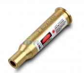
To do the same with a rifle,.....get a beam to project from the bore, on the centerline of the bore, the laser would be the shape of the cartridge and be adjustable so as to be concentric and square to the bore.

Lasers like that are available in many popular calibers so as to "bore sight", that is "align" a telescopic sight, (scope), to the bore.

Of course the optics are on a different plane.
On the horizontal axis the centerline of the optics are parallel with the centerline of the bore, on the vertical axis the centerline of the optics and the centerline of the bore meet, (intersect), at a distance where the two cross because the optics are pointed down at an angle.

Here is a picture of one of those units.
 

Attachments

  • Laser Cartridge.jpg
    Laser Cartridge.jpg
    31.1 KB · Views: 277
Yes you are correct the beam is not colinear with the cue stick's center axis. From a top view however, it is aligned through the axis. The design I have sketched is more useful because the beam can travel "through" the CB and anything else in its path that is level with the sticK.

Are you arguing semantics of the word centerline? Or do have an idea to share.

We are brainstorming here... No bad ideas.
 
Are you arguing semantics of the word centerline? Or do have an idea to share.

No, no of course not.
Not semantics, it's just terminology.

The beam would be parallel to, and centered over, the cue , but it would not be in alignment with the cues centerline.

The same relationship as as scope on a rifle.
 
Ok, lets put the terminology to rest:

The rotating laser would form a plane. This plane would be normal to the slate. The cue stick's longitudinal axis of symmetry would lie on this plane. The plane would be invisible to the naked eye, except where it is intersected by a physical object, such as the stick or the CB, or the table cloth, where it would project it's path onto this physical object surface.

How about that ? :):)
 
Fantastic!

Stan Shuffett

Stan,

Do you think a design like this would be useful?

I was kind of thinking it could be used by you (or another CTE expert), and you would line up with your visuals, then pivot to the hard stop, then shoot.

The fixture would ensure the pivot point was fixed, and the pivot distance [the half tip] was fixed, and there was not a subconscious adjustment going on.
 
Last edited:
Ok, lets put the terminology to rest:

The rotating laser would form a plane. This plane would be normal to the slate. The cue stick's longitudinal axis of symmetry would lie on this plane. The plane would be invisible to the naked eye, except where it is intersected by a physical object, such as the stick or the CB, or the table cloth, where it would project it's path onto this physical object surface.

How about that ? :):)

Pretty close.

The cue stick's longitudinal axis is of course symmetrical to the cue.
The challenge is to locate the laser so that the beam is symmetrical to that axis.
No need to rotate the laser. The principal of what you're trying to accomplish is clear, but the laser, do to error in the concentricity and squareness of the inner element, may draw a circle, so to speak, when rotated.
So the question is how to be assured the the inner element is concentric and square to the housing.
Not to bad to solve. You generate a sleeve that the laser slides into with room to spare. The sleeve has 4 set screws near the front and four set screws near the rear. You center the laser buy eye with light tension on all the screws. You place the sleeved laser into a V block, turn on the laser, aim it at a vertical surface, (a wall), and rotate the assembly in the V block to see what you have. Adjust the screws to bring in the concentricity and squareness between the beam and the sleeve.
Now that the beam is aligned with the sleeve you simply mount the sleeve in a V on the fixture that is parallel and square to the cue.
Of course you have to keep in mind "accumulative error". When you do the adjusting of the screws you should do it at a pretty good distance. A greater distance of course than the fixture will serve when it is used. That is to say if you have things tuned in nicely at 15 feet it will be outstanding at 4 feet.
Again, like a rifle.
Carefully placed shots from the bench at 25 yards appear to be nicely centered. At 50 yards it may already be noticed that the group is tending to the left. At 100 yards it is a full inch to the left, at 150 yards the group will be looking more like 1 1/2" to the left.
A small amount of error at the point of departure will only get worse over a longer distance. Thus the term, "accumulative error".
That is why you zero a rifle at a practical distance for the caliber at hand. Farther or closer then becomes only an issue of elevation due to gravity.
Of course a laser will stay stay on a straight path because it is not affected by gravity the way a projectile is.
So you rotate the laser in it's adjustable housing and tune it in. Once tuned in there is no need to rotate it any more. The beam will stay concentric and square to the sleeve/housing unless it is dropped, jarred, or someone messes with the screws. If that happens, simply re-tune it and re-mount it.
 
RMS:

I understand, you are basically using a dual 4 jaw chuck methodology to align the beam. That is a great idea.

Without getting into the technical issues of how to align the beam, a higher level functional question for you:

If I'm understanding you completely, you are describing a typical laser pointer (aligned precisely). This forms a 1 dimensional straight line.

What I am describing is a 2 dimensional plane. That projects a line onto any surface that it intersects.

The main difference between the two, is the 1 dimensional line would not go "through" the CB, or the stick, or the OB. It would be blocked by the first thing it hits. Getting this line to be visible on multiple locations of interest for this machine is problematic.

The plane type laser would not have this problem.

I don't know if you've fooled around with 1 dimensional laser type levels/pointers on a pool table before to line up shots. I have, and they are awkward to use, because the beam only touches one thing at a time.

As far as aligning a rotating plane type laser, that too could be made adjustable.
 
Back
Top