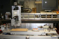
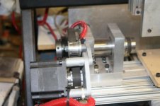
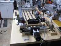
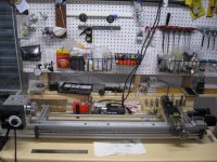
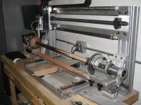
My new Inlay Machine

I bought the Gecko 540 with the control box prebuilt with a power supply and switches from Deepgroove1.com. I popped the cover off before I set it up. Very pleased with the wiring. All the wire to spade solder joints had the spades fully covered with solder.
 
I bought the Gecko 540 with the control box prebuilt with a power supply and switches from Deepgroove1.com. I popped the cover off before I set it up. Very pleased with the wiring. All the wire to spade solder joints had the spades fully covered with solder.

Great for you.
Xylotex is a piece of kaka.

ps
Sorry Royce. Jeesh, I'm horrible with names.
 
Looks like a nice machine Dan and great effort on your part.
Now let me ask you this, How many inlays can your inlay lay if your inlay can lay lays?
Answer that and I will send you a genuine Canadian shrubbery.
 
Last edited:
Great for you.
Xylotex is a piece of kaka.

ps
Sorry Royce. Jeesh, I'm horrible with names.

No problem Joey, I've been called worse! :wink:

I have several Xylotex systems in my shop right now, but am replacing them with the G540's. The Deepgroove system that DAnO used is a very good systeme and at a very good price. If I need to go ground up with a G540, it will be from Deepgroove. Right now, I'm just replacing the driver boards and using my existing motors and power supplies. Yes, they are only 24V, but the difference between them and the 48v power supplies is mostly on the rapids and since the gecko will move faster than the xylotex even with the 24v P/S, it really doesn't hurt me any.

I've used the Xylotex for years and they have been very good to me. Back when I started with DIY cnc, the only drives Gecko had were the G201's. G201's are individual drives which require much more work to setup and get going. I opted for the xylotex because of price and simplicity. I can't complain as they have built me quite a bit of products over the years, but the G540 is a better unit. The individual drives are replaceable separately, and the mid band resonance reduction makes them run much smoother and much better.

Merry Christmas everyone!
 
cnc

And Oh My I cant forget to thank many of you here on Az for your help and Ideas.
Royce has done so much to help me with design ideas and cnc knowledge in general. Along with Bob Dzuricky, Mc2, Williecue, Rob @BPQ , Lee at brianna and Mark Smith.

Thanks to all of these great people my machine is up and I am now trying my best to learn the software.

Thanks again to all of you and Merry Christmas

Dan Marish
Marish Cues
 
Very nice. Guess I will go shoot some pics of mine. Anyone else with home built machines? lets see 'em.

Dan

Here is a short video of the newest one that I made. I believe it is sold. We take it to the new owner next week.

Jim.
P.S. this is a video. Just click on it. Sorry about the quality.

 
Hello Jim

Very nice machine.

I'm going to get my canon out later today and try to shoot a few pics.

Have you worked much with optical home switches?

I picked a few up but now need to figure out a circuit or board to tie them into main board.

Dan
 
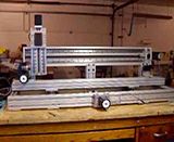
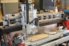
My ugly little cnc home built from pieces and parts. sorry for poor photos.
 

Attachments

  • cnc1.jpg
    cnc1.jpg
    42.7 KB · Views: 453
  • cnc2.jpg
    cnc2.jpg
    38.3 KB · Views: 449
  • cnc4thaxis.jpg
    cnc4thaxis.jpg
    29.7 KB · Views: 450
Nice.

Looks like you did a nice job on that machine. I have used optical home switches. I will not run another cnc without them. As far as hooking them up? It shouldn't be too hard. I believe that you can even wire them up in series if you know what you are doing and only use one input with Mach3.

Jim.
 
I know I need some current limiting resistors in series with the photodiode to make sure there is enough resistance on the load (output side) to keep below the maximum collector current of the sensor.

I've read a few posts on the CNC Zone, but I am a bigger dope on electronics than on anything else.

I've read to use around a 330 ohm resistor but not sure how to wire each one and then put in series. I saw a project where they built a small board , ran all three switches to there, which tied the three together , then ran the leads to the break out board.

So if someone has the correct or an easier way let me know.

Damn I'm such an electronics goof ball.

Guess Mom was right. I should have gone to school instead of the pool hall.
Can you send me the brand and part number of your optical switches? Even better would be a url to the manufacturer's data page. I just spent some time learning about these from an electronics engineer. If they are similar to mine, I think I can help get you moving forward.

Gary
 
Last edited:
Here's my CNC Taper bar - a work in progress.

It's an X-Y mill built onto the backside of my lather. I'm sure that down the road I'll be moving to a full X-Y-Z setup so I can learn to do inlays, but one step at a time for now.

Design goals are:
1) Be able to move between manual and computerized operation easily
2) Be able to try new taper curves but revert back to others by simply loading a different G-Code program.

I haven't finalized how I will attach the Y-axis stepper to the cross-slide, so it is not attached at this point. The Y-axis stepper and cross-slide move up and down the X-axis on twin (indentical) leadscrews. X-axis travel is something over 30 inches. Y-axis travel is 2 inches. Control hardware is from HobbyCNC.com. Control software is Mach3. I don't have a CAM program yet - I simply edit the G-Code for the time being.

I've picked up help and ideas from so many here on AZB that I couldn't begin to name you all - but THANKS to all for their contributions.

Gary
 

Attachments

  • Cue Lathe CNC Taper #1.jpg
    Cue Lathe CNC Taper #1.jpg
    96.6 KB · Views: 433
  • Cue Lathe CNC Taper #2.jpg
    Cue Lathe CNC Taper #2.jpg
    98.8 KB · Views: 434
Great taper setup Gary. Great idea.

I still have some 4ft rails and a 4ft bed to put to use some how. This looks interesting.

Thanks for your photos.

Dan
 
Can you send me the brand and part number of your optical switches? Even better would be a url to the manufacturer's data page. I just spent some time learning about these from an electronics engineer. If they are similar to mine, I think I can help get you moving forward.

Gary

Sorry this took longer than I planned, but I think this will answer your questions.

One thing to keep in mind is that there are two circuits here - one circuit (+5V) powers the LED light in the optical switch.

The other circuit is between the Output and the Ground. This is the signal line that triggers your CNC controller to turn the X, Y, or Z axis motor off when the LED light gets interrupted.

You can use 4.6-12V where I have indicated 5V. I'd keep it down to 5V or 6V. You can use a simple wall-wort power supply for this (make sure it is DC voltage). Read your controller manual, it may have a 5V supply circuit built in.

You may also need a 5V DC supply to power the signal circuit - again it depends on your controller.

I have to have both for my controller, but I think the Gecko G540 supplies one or both for you.

Hope this helps!

Gary
 

Attachments

Here is an end pick of my machine. I was planning on 8” of travel in my Y for no particular reason. I could feel a little flex in my X frame so I added the two end gussets. They make it rock solid but now I only have 4.5” of travel.

I’m concerned about contaminates falling on my Y lead screw. For now I installed some precision purchased cardboard pieces to cover up the lead screw. (Busch Light 30 pack can separators.) My lead screws have a factory Teflon coating on them so I hope this is enough. Haydon Kerk told me I would be fine as long as the material is not abrasive. Define abrasive? I know plenty of players that are abrasive but they can’t hurt my lead screw. For my Y, I may come up with some sort of collapsible bellows covering on the back side of the screw and a U channel on the front since I need to travel out to my end bearing.
 

Attachments

  • IMG_3829.JPG
    IMG_3829.JPG
    77.3 KB · Views: 336
Back
Top