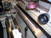
Showing the spring loaded cross-slide.........You might have to loosen the gibs slightly for free movement.
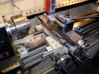
One thing I'm not fond of is having the compound slide perpendicular....I'm always pinching my knuckles on the cross-slide dial. Oh well.

One thing I'm not fond of is having the compound slide perpendicular....I'm always pinching my knuckles on the cross-slide dial. Oh well.
Attachments
Last edited:
")