Yes that's exactly what I intend to do...
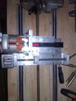
please put a limit switch on x right before those big ass chucks! wow
It's funny because I setup a dedicated computer to just run the g-code and mach3 software and it doesn't have a monitor or keyboard.
I just remote desktop into it to control the computer.
I use autodesk inventor for the majority of the actual work and programming and then just export the faces and import them to create the g-code.
So I will be using my main computer for that and then just load the g-code over the network and run the program through remote desktop.
The problem I have already ran into is that my main computer's wireless card (my router is in my living room, my shop is in my garage) is on the fritz and cuts out at inopportune times.
I have discovered that if you are jogging in mach 3 when the connection stops, mach3 just continues right on jogging in the same direction indefinitely until it receives a new command.
A couple of times I have had to switch off the power to the controller to stop the jogging.
So I will probably later today go to radio shack and get a 5v momentary switch to connect to the controller as a stop switch on the x axis.
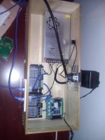
I know that everyone seems to like the gecko 540, that's quickly becoming the industry standard for us DIYers, but this controller has a lot of cool, easy to use features and is comparable to the gecko.
Plus, I like the way it wires up to the motor drivers.
From what I've seen with the gecko, you don't use a separate connection for the enable +5v, and with mine you do. So I'm actually using 6 wires to connect from the controller to the driver. three for the common grounds and 3 for the pulse +, Direction + and Enable +.
It seems to be working great but will take some time to know how well it works for sure.
Jaden

")