Hi,
Over the last 3 weeks I have been building my first big CNC cue with 151 inlays and the last 5 days I have been pulling teeth over analyzing everything but the Kitchen sink as my X Axis was missing steps and did not correctly align on the Y during A axis rotation as described in my last thread seeking advise.
Tim Prince told me that he thought my problem was mechanical and he was very right. The kicker in this nightmare that just ended for me was I was getting good results on some test pieces and then it would go bad again.
Root Cause:
I was slipping steps on my X because I was using profile slots in the pocket corners so my sharp parts fit as a separate feature before cutting the pocket. I cut my pockets in two even elevation cuts to .125 with a .0313 mill. I cut my slots in one elevation pass at .125 and was getting push off thereby causing the stepper to get out of time a little. This was the reason the offset error was so consistent. The same push off was happening every time.
In the end it was Tim's shared thoughts that tipped me off because at 4 AM this morning I realized that high pitched noise I had been hearing during full depth slotting was giving too much resistance to the stepper and it was in the X directional plane. Duhhhh! I had been hearing that noise and should have known better.
Corrective Actions:
Reconfigure the pocket drawing to create a tool path that is slightly bulbus at the corners instead of making the slots to alow the sharp corner parts to fit and eliminate the slots.
I did a little rounding on the Cad drawing and verified the toolpath would work with the .0313 mill and in 31 minutes I had 12 evenly displayed pockets cut using two elevation depth cuts with no push off pressure to my X. Poof!!! The problem is now just a passing thought.
Lessons Learned:
I have been using the slotting method for sharp corners and have not had any problems because they where set in point stock or a butt sleeve and the X off set was never seen when it is 90 or 72 degrees apart. It is like hub caps on a car you can have one set on one side of your car and a totally different set on the other and no one would notice it.
The 5 day ordeal has taught me how truly accurate my Unique Cue Monster is and that my Controller, Computer, Software and Mach 3 DRO is very adequate for my present use. ( I still want to get a HAAS when I sell my pool hall ):help:
The reason I was getting varying results is that like a idiot I was sometimes using maple instead of ebony to make my tests. ( I knew better ) Hence the tool resistance / push off did not happen unless I was in the harder ebony material.
A huge benefit that I have gained is that instead of loading 72 features on my Cam Tree for this butt sleeve, it is now down to 36 features to do 36 pockets as the slot operation per pocket is gone. I am also back to speed with my velocities and acceleration rates and everything is cutting faster and like butter.
So in the final analysis this 5 day ordeal has helped me to be more efficient and like a pilot I can trust my instruments is bad weather. That is until the next Gremlin hits the fan and I start questioning everything under the sun again.
Thanks again to Tim and all who tried to lend a hand as it is appreciated. I hope my bad experience can help other CMs avoid the rat hole I fell into.
Rick G
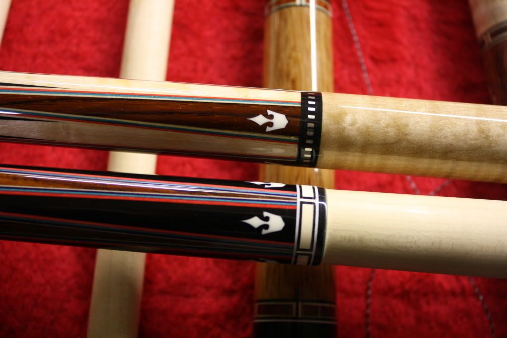
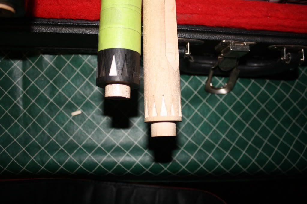
Here are the 12 successful compensated pockets at 30 degrees on the A lined up perfectly on the Y. I dropped in a part with sharp corners at the 0 position.
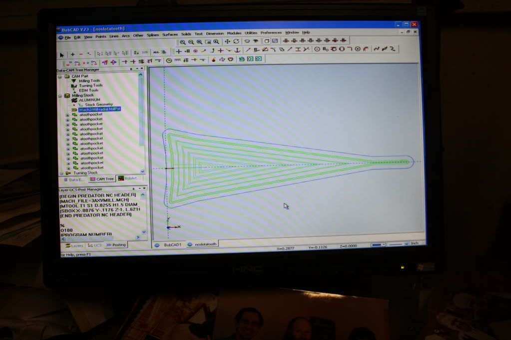
Here is my amended pocket Geometry that I did last night. I rounded it for sharp corner insertion instead of my old slotting method. Live and learn!
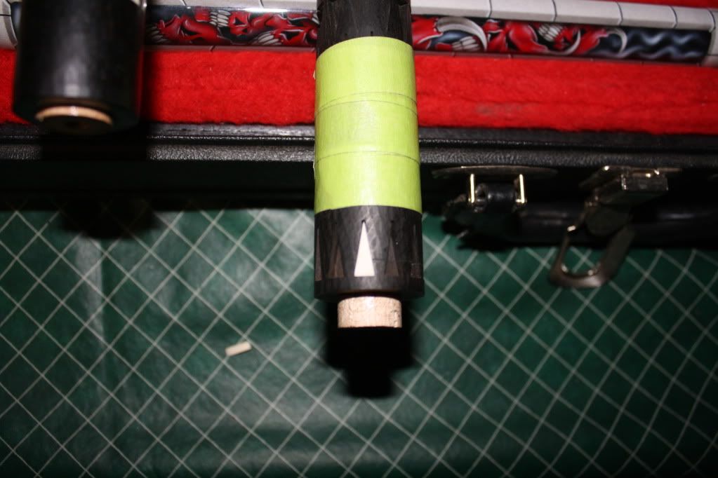
Here is one of the maple test pieces that did not step out because it was softer than ebony and did not throw off steps. I needed that added to the mix like I needed a hole in my head.
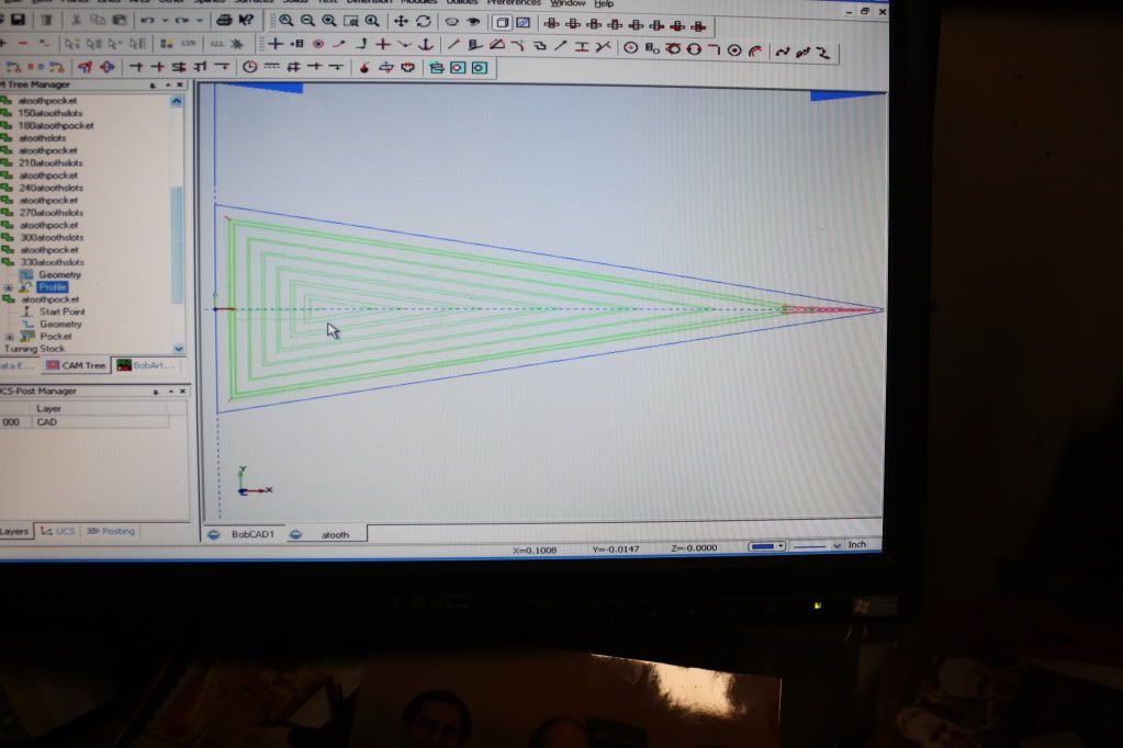
Here is my old geometry that used profile lines to extend the pocket allowing sharp corner insertion. RIP !!!
Over the last 3 weeks I have been building my first big CNC cue with 151 inlays and the last 5 days I have been pulling teeth over analyzing everything but the Kitchen sink as my X Axis was missing steps and did not correctly align on the Y during A axis rotation as described in my last thread seeking advise.
Tim Prince told me that he thought my problem was mechanical and he was very right. The kicker in this nightmare that just ended for me was I was getting good results on some test pieces and then it would go bad again.
Root Cause:
I was slipping steps on my X because I was using profile slots in the pocket corners so my sharp parts fit as a separate feature before cutting the pocket. I cut my pockets in two even elevation cuts to .125 with a .0313 mill. I cut my slots in one elevation pass at .125 and was getting push off thereby causing the stepper to get out of time a little. This was the reason the offset error was so consistent. The same push off was happening every time.
In the end it was Tim's shared thoughts that tipped me off because at 4 AM this morning I realized that high pitched noise I had been hearing during full depth slotting was giving too much resistance to the stepper and it was in the X directional plane. Duhhhh! I had been hearing that noise and should have known better.
Corrective Actions:
Reconfigure the pocket drawing to create a tool path that is slightly bulbus at the corners instead of making the slots to alow the sharp corner parts to fit and eliminate the slots.
I did a little rounding on the Cad drawing and verified the toolpath would work with the .0313 mill and in 31 minutes I had 12 evenly displayed pockets cut using two elevation depth cuts with no push off pressure to my X. Poof!!! The problem is now just a passing thought.
Lessons Learned:
I have been using the slotting method for sharp corners and have not had any problems because they where set in point stock or a butt sleeve and the X off set was never seen when it is 90 or 72 degrees apart. It is like hub caps on a car you can have one set on one side of your car and a totally different set on the other and no one would notice it.
The 5 day ordeal has taught me how truly accurate my Unique Cue Monster is and that my Controller, Computer, Software and Mach 3 DRO is very adequate for my present use. ( I still want to get a HAAS when I sell my pool hall ):help:
The reason I was getting varying results is that like a idiot I was sometimes using maple instead of ebony to make my tests. ( I knew better ) Hence the tool resistance / push off did not happen unless I was in the harder ebony material.
A huge benefit that I have gained is that instead of loading 72 features on my Cam Tree for this butt sleeve, it is now down to 36 features to do 36 pockets as the slot operation per pocket is gone. I am also back to speed with my velocities and acceleration rates and everything is cutting faster and like butter.
So in the final analysis this 5 day ordeal has helped me to be more efficient and like a pilot I can trust my instruments is bad weather. That is until the next Gremlin hits the fan and I start questioning everything under the sun again.
Thanks again to Tim and all who tried to lend a hand as it is appreciated. I hope my bad experience can help other CMs avoid the rat hole I fell into.
Rick G
Here are the 12 successful compensated pockets at 30 degrees on the A lined up perfectly on the Y. I dropped in a part with sharp corners at the 0 position.
Here is my amended pocket Geometry that I did last night. I rounded it for sharp corner insertion instead of my old slotting method. Live and learn!
Here is one of the maple test pieces that did not step out because it was softer than ebony and did not throw off steps. I needed that added to the mix like I needed a hole in my head.
Here is my old geometry that used profile lines to extend the pocket allowing sharp corner insertion. RIP !!!
Last edited: