You are using an out of date browser. It may not display this or other websites correctly.
You should upgrade or use an alternative browser.
You should upgrade or use an alternative browser.
Cuemakers please post your inlay pictures
- Thread starter brianna187
- Start date

Wow, roughing with a .015?I would have probably done an extra tool change and used a .02 or .03 for the roughing.
6 of one half-dozen of another though.... the results look great.
If I'm having trouble lining up on the center of the points, I'll put a 60 degree index cutter in, so that I can really get close when lining things up.
I'll sometimes put the cutter on one side, zero out the Y axis, put the cutter on the other edge, (effectively measuring the width of the inlay area) then reset your Y to exactly half of the number you get. That should center you up nicely. If you have a fourth axis, you can do the same with the A axis instead.
On my machine, I have an exact number from the hard stop for zero along my Y, so I can alway find center that way... I just have to dial in the A if I reset the cue.
I rough with a .015 because the parts are actually quite small. I also don't like to leave a lot of material for the .010 to have to go through when it cleans up. If I go slamming into an area, there's a good chance I'll break the bit. At this point, I rarely use anything over a .015, even for cutting out parts. I rarely break bits unless I drop or do something stupid.
Here is how I find the center of the point. I align my cutter on the edge of the veneer closest to the point, so it's just touching the edge. Rotate the cue to the other edge and do the same. Take that measurement, divide by two and that's my center point. Then I drill a small hole where the inlay will be and measure to each side. I have a 200x microscope that I use to get a good view of where the cutter is when I'm doing the alignment.
For the spaces between the points, I just eye it with a larger cutter. The gap between my points isn't very big, so a 0.313" cutter fits in there quite nicely.
One thing I've found with measuring from side to side is you can get different measurements pretty easy, just by moving twisting the caliper a little bit. The angle I'm working at, it's hard for me to trust that measurement. I've tried that method aligning where the ring meets the point so I'm always measuring straight, but it doesn't work as well for me either.
When replacing an inlay, I simply align with certain points on the inlay and move from there to where the center should be. I then cut a new inlay over the top, leaving a .010" border and take a look to see what's left. If I need to make any adjustments from there, I will and take a little more off, until I'm satisfied the border is concentric all the way around the pocket. Once that happens, I will cut out the rest of the part. Most of the time when I'm done, I won't have to change the size of the part at all. If need be though, you can always make the part .0005-.001" larger so that you're going into a clean pocket.
Top picture is all I can show of Tikklers Ivory cue.
scott the finish looks great....and the joint protectors look awesome...i cant wait to get that baby back home....thanks mickey
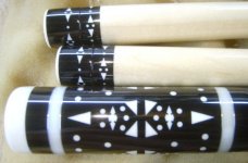
This is not a inlay,but it is done with mach3.
these are some handles with a grapevine splice.
dark coco with zebra
tulip with purple heart
zircote with yellow heart
bill
now thats pretty bad ass
Oh My ... we are getting some very high level work posted here.
I am very impressed with the artistestry that has been shown.
Now I am embarrassed to show my humble inlays.
They done even come close to this level.
Hope others will post their CNC work.
Always enjoy seeing fine workmanship in a cue.
I am very impressed with the artistestry that has been shown.
Now I am embarrassed to show my humble inlays.
They done even come close to this level.
Hope others will post their CNC work.
Always enjoy seeing fine workmanship in a cue.
Hi,
Great Post & nice work on exhibit.
I have read a couple of things about lining up the spindle with the centerline of the cue. My friend is a CNC pro and does this stuff for a living on a level that is a 1000% more involved than our pockets and inlays.
He told us to machine an alum datum block and place it behind the back side of the alum plate that is the base for the spindle. When you move the X axis back so the spindle base just touches the datum block that becomes wedged to the back frame, you have created a repeatable home position. Clear and zero set your home position to .0000 and then move on X to align your mill bit with your center point of your dead center and write down that reading on the X axis. Clear home to .0000 and you are aligned on your center line. Now every time you want to get on the cue's centerline, touch off on the block and take the spindle over to the number you wrote down and clear home to the .0000 reference.
As far as the Y axis is concerns, we just measure and eye ball for the other center line of the geometry.
Using the datum block gives you fast control for center line finding.
We also fabricated a milled and dowel pined shim plate that installs under the tail stock block on our Cue Monster that compensates for the vertical off set that is created when a tapered cue in mounted between centers. This makes the cue flat so that depth floor of the pocket is uniform when observed in elevation view over the Y axis.
Rick G
Last edited:
")

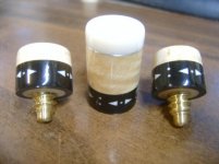
Here are some inlays I screwed up. Look at the cue in the last post and you'll see the mistake.
Now you gotta build a cue to match those caps.

RBC
Deceased
Hi,
Great Post & nice work on exhibit.
I have read a couple of things about lining up the spindle with the centerline of the cue. My friend is a CNC pro and does this stuff for a living on a level that is a 1000% more involved than our pockets and inlays.
He told us to machine an alum datum block and place it behind the back side of the alum plate that is the base for the spindle. When you move the X axis back so the spindle base just touches the datum block that becomes wedged to the back frame, you have created a repeatable home position. Clear and zero set your home position to .0000 and then move on X to align your mill bit with your center point of your dead center and write down that reading on the X axis. Clear home to .0000 and you are aligned on your center line. Now every time you want to get on the cue's centerline, touch off on the block and take the spindle over to the number you wrote down and clear home to the .0000 reference.
As far as the Y axis is concerns, we just measure and eye ball for the other center line of the geometry.
Using the datum block gives you fast control for center line finding.
We also fabricated a milled and dowel pined shim plate that installs under the tail stock block on our Cue Monster that compensates for the vertical off set that is created when a tapered cue in mounted between centers. This makes the cue flat so that depth floor of the pocket is uniform when observed in elevation view over the Y axis.
Rick G
Rick,
That sounds like a good way to repeat your position.
Have you ever thought of using home switches? I don't mean the mechanical switch type, but the Photo optic type. They are repeatable to very small numbers and are pretty easy to setup. Once you have them, you just reference your machine to home and setup a work offset to get you to your zero position. You can use different offsets for different work stations on your machine. Currently all our machines are for turning so we don't have as much of a need for them, but I am building a couple of machines for inlay and other things, and they will both have optical home switches.
Another cool thing about good home switches is that you can build a tool changer if your spindle has an air actuated collet. These are really cool!
I'm not sure if this is a bad idea or not;
My plan is to home the machine and actually make the CAD as a drawing replicating my machines bed layout. The indexer/4th axis would then be placed at a fixed place where i actually draw my inlays placed at this point in the CAD drawing.Tailstock of the setup is the only thing moving... Now, if I mount my cues with a recut fixture I had a plan that this would make me able to recut inlays with the accuracy of the machine.
Not quite there yet but that was my plan at least..
The negative part is that I would be drawing the inlays in a CAD drawing which is hugh compared to the inlays, but I'll just zoom in on my "inlay area" and I hope to be fine...
Anyone tried it? Any obvious flaws which I havenot thought of....
Kent
Rick,
That sounds like a good way to repeat your position.
Have you ever thought of using home switches? I don't mean the mechanical switch type, but the Photo optic type. They are repeatable to very small numbers and are pretty easy to setup. Once you have them, you just reference your machine to home and setup a work offset to get you to your zero position. You can use different offsets for different work stations on your machine. Currently all our machines are for turning so we don't have as much of a need for them, but I am building a couple of machines for inlay and other things, and they will both have optical home switches.
Another cool thing about good home switches is that you can build a tool changer if your spindle has an air actuated collet. These are really cool!
Royce,
You sound like your way ahead of me on the CNC skills. I am going from Kindergarten to First grade at this time. I wish I had something with a tool changer, it would be awesome and I would approach everything in a different way. Right now I am just happy to do a pocket and an inlay contours that look good.
The switches sound really cool and I am sure they are deadly accurate. If you are CNC turning, it sounds like your production repeatability is tuned in to less that + or - .001.
Thanks for letting me know about those switches. Maybe some day I will have some sophisticated machines. Who knows, now a days some high end CNC Lathes are going for cheap at auction. I was at the Schuler Auction and they had a CNC Lathe that I know Ray bought used for over $ 50,000.00 and it went off for $ 3500,00. I did not have the shop space and never gave bidding on it a thought.:yikes:
Thanks for you comments, I appreciate learning more details about CNC.
Rick G
PS. I do all of my cues with solid maple cores and am totally committed to that discipline. I just viewed your website and I see we share that philosophy.
Last edited:
Rick,
That sounds like a good way to repeat your position.
Have you ever thought of using home switches? I don't mean the mechanical switch type, but the Photo optic type. They are repeatable to very small numbers and are pretty easy to setup. Once you have them, you just reference your machine to home and setup a work offset to get you to your zero position. You can use different offsets for different work stations on your machine. Currently all our machines are for turning so we don't have as much of a need for them, but I am building a couple of machines for inlay and other things, and they will both have optical home switches.
Another cool thing about good home switches is that you can build a tool changer if your spindle has an air actuated collet. These are really cool!
Having a home base is great for moving the spindle to work on a cue. It works when working on a blank pallet when all decorations are inlayed and on perfect centers. When inlaying between points or boxes they are never in the exact same position and the start point for each inlay needs to change. The adjustment is so small it's not noticeable in the finished cue. If the inlay is not centered to its surrounding material it will show. I don't see how home switches or a common start point help in most situations.
Last edited:
Having a home base is great for moving the spindle to work on a cue. It works when working on a blank pallet and all decorations are inlayed. When inlaying between points or boxes they are never in the exact same piston and the start point changes on every inlay. The adjustment is so small it's not noticeable in the finished cue. If the inlay is not centered it will show. I don't see how home switches or a common start point help in most situations.
This is especially true when inlaying full splice points.
Home switches would be really nice, but I never got around to setting them up. Like I stated earlier, I have a number I use to center Y from a hard stop, I just turn the controller off, dial the y into the stop by hand, then fire it back up and run an incremental move to center. This gets me close enough that I haven't bothered with homing.
One thing I've been wanting is a spindle switch, so I can turn the spindle on and off in the G-code. That would be really handy.
One thing I've been wanting is a spindle switch, so I can turn the spindle on and off in the G-code. That would be really handy.
Home switches would be really nice, but I never got around to setting them up. Like I stated earlier, I have a number I use to center Y from a hard stop, I just turn the controller off, dial the y into the stop by hand, then fire it back up and run an incremental move to center. This gets me close enough that I haven't bothered with homing.
One thing I've been wanting is a spindle switch, so I can turn the spindle on and off in the G-code. That would be really handy.
I edited my last post.
I'm adding home switches to CNC I'm building and they'll have many benefits. The problem with CNC machines is they don't allow for human error. That's where the operator needs to adjust for perfection and starting from a home base doesn't work for some inlays.


