I'm with Royce on this one.
If we simply look at the tolerances allowed on the threads themselves, we can see that 2-3 thou is nothing. Easy to say that, but here's the reason:
Here are the thread tolerances for 5/16-18 UN 2A class threads because the 5/16-14 is not in any of the books, but likely to follow the 2A or possibly 1A class- not 3A- which has a lower tolerance and would be very difficult to screw together (if machined perfectly- and would need tools for assembly 99% of the time otherwise), assuming both the internal and external are 3A class... Plus 5/16-18 is used by several cue makers, and 3/8-16 threads have even more tolerance on them.
So, with our 5/16-18 example we have a range on major diameter of 0.3113" max OD to 0.3026" min OD, or 0.0087" 'range' to an acceptable 2A class thread. Assuming you are not using worn taps and dies and work carefully, lets hold it at a range of 5 thou (0.005"). Unplated, purchased 2A class threaded items should easily hold this.
Then there's the Inside thread: Max ID is 0.265" and min ID is 0.252", for a range of 13 thou. Lets hold that at 10 thou (0.010") for the sake of this discussion.
Add those together, and we have 15 thousandths (0.015") of 'slop' acceptable to engineering standards for threads.
If your pin is out 0.002" you still have over 10 thou slop in there. Realistically you could be out 0.002" for 3.75 times the diameter (1.1718"), and still be 'straight'. Since we don't have thread engagement for that distance, we are fine; even more so if TIR is 0.002" measured at the END of the pin- you could go another inch longer and still be fine. (plus your threaded rod stock is probably not that straight to begin with anyway- do you put it between centers and verify straightness?)
If you want your pin threads TRULY straight and in alignment with the center of your cue (or whatever), you have to single point them onto a plain rod between centers. That aligns the thread with the centerline of the cue. There is no other absolute way to do it. Those who cut threads into wood for their shaft probably have the best aligned threads in the shaft. However, if the pin is purchased, there is tolerance on it. There has to be. Those who turn their cue on the center of the pin are relying on the pin to be absolutely straight, which it may not be.
Threads should not be relied upon for alignment. They can be (but still a risk), if a 3A class thread is used for both the male and female threads, but it is not good practice, and even so, you STILL have tolerance in those tight 3A threads to allow them to function properly without binding.
In summary, threads are a mechanical connection used to pull the pieces together. A well made pilot keeps things aligned, as well as parallel faces. Having both (parallel and piloted) is the best way in my opinion.
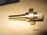
Pics below of a mandrel I made last night. It fits into the butt of the cue and registers on three diameters to hold 'center'. It of course has tolerance on it- 0.002" under the diameters I machine into my butt cap so it slides in without interference (a true slip-fit would be 0.003 under). It is also (single point) threaded; however I deliberately cut those threads undersize so they do not put any side pressure on the mandrel and bring it out of center. They are only there to keep the mandrel from falling out of the cue really...